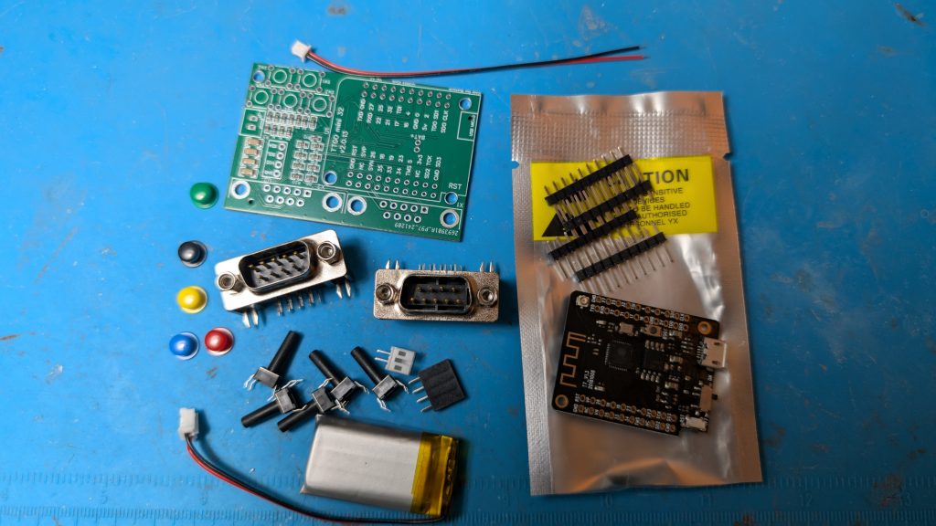
The unit comes with all the parts you need except the case and solder. you will need to 3D print the STL file, assemble the parts, and solder the components. The Firmware is already loaded so you do not need to load any firmware.
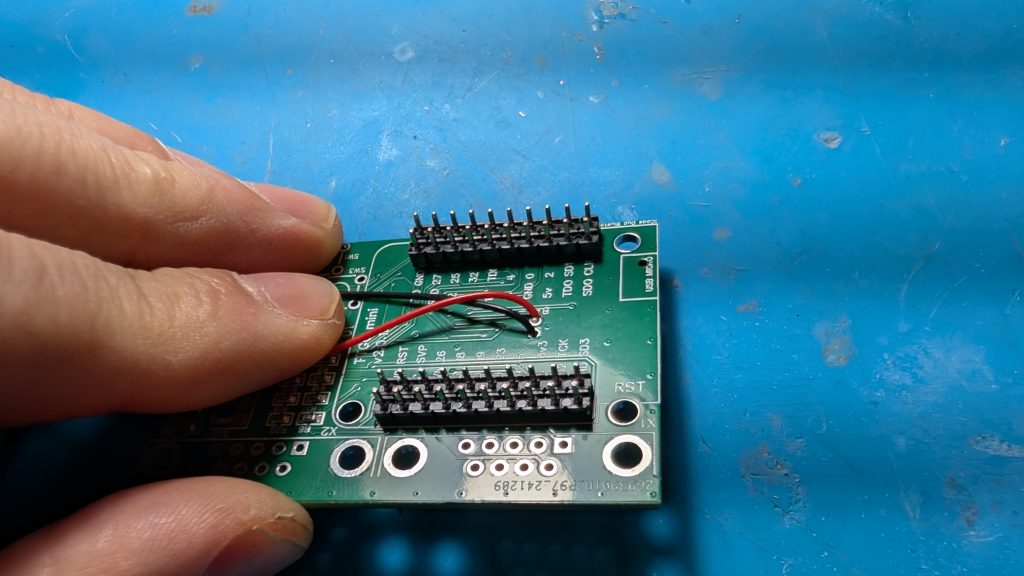
Step 1
Insert the power connector cable to the PC board (Red to the BAT+ hole) and solder it from the bottom side. Also solder on the white male battery socket on the PC board as shown.
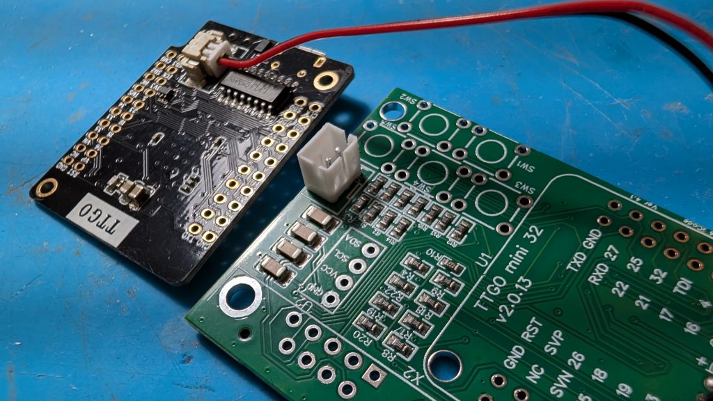
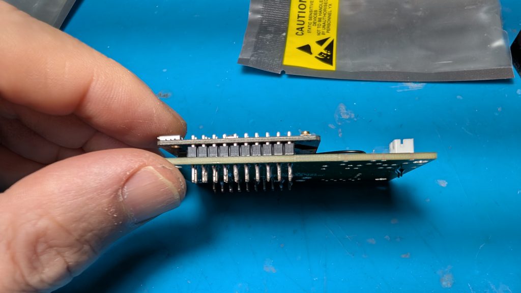
Step 2
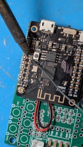
Place the daughter micro controller board on the PC board and make sure its level. there will be a small gap as shown on the left picture. The solder it as shown starting with the inner pins on both sides with soldering iron coming from the outside. Be careful as you don’t want to touch any of the components on the micro controller board with your iron.
Step 3 & 4
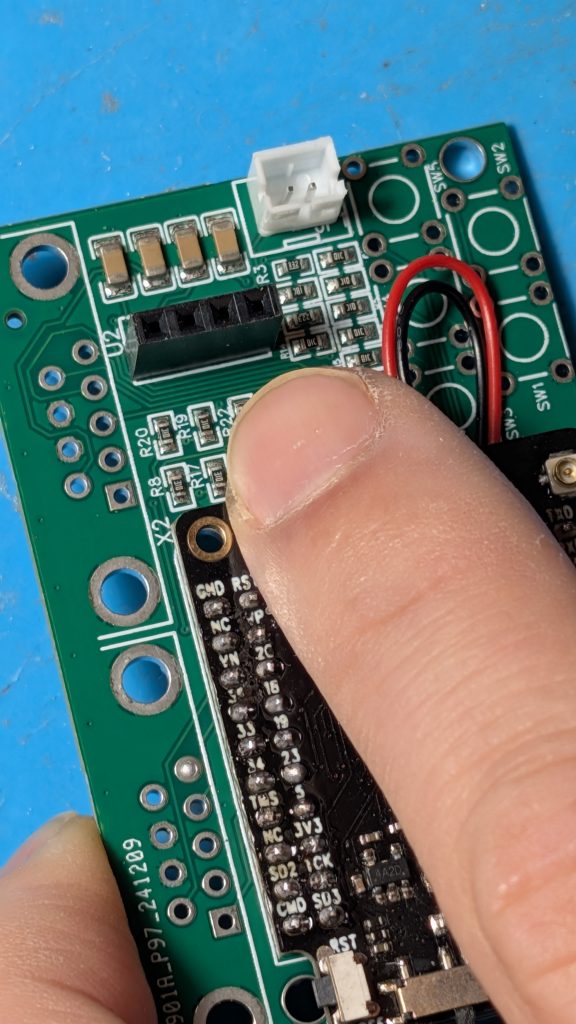
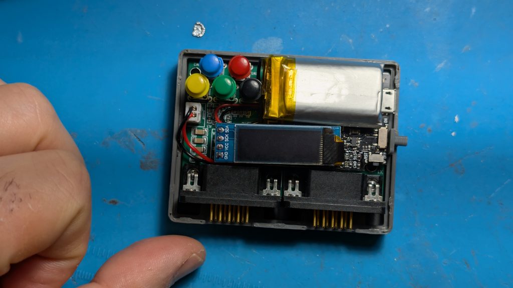
Solder on the black 4 pin female connector. This is for the screen you will place on later.
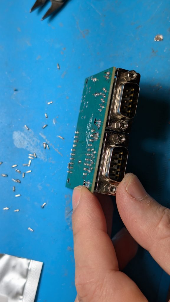
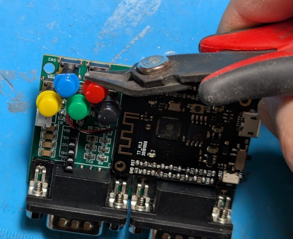
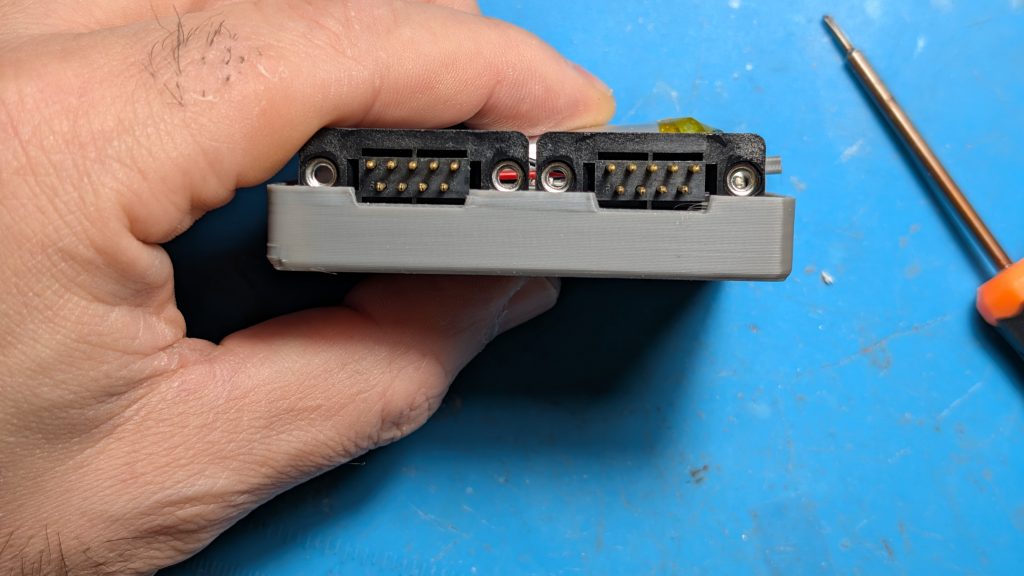
Solder on the two 9-pin right angle connectors as shown.
Step 5
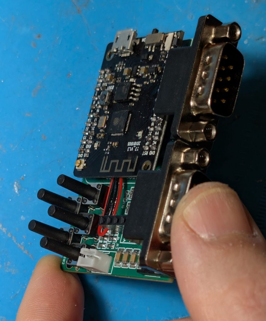
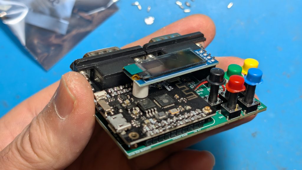
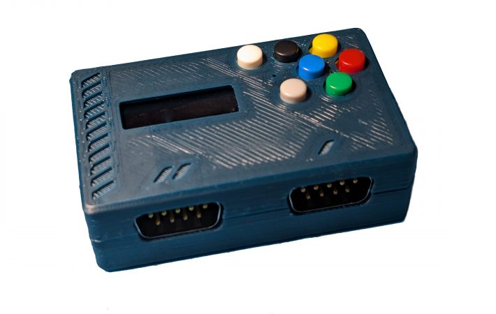
Place the the 5 switches and make sure hey are straight and then solder them on. Place on the colored caps and if you place to use the case, trim the edges of the blue and red caps as shows so they don’t get in the way when we close the case later on.
Step 6
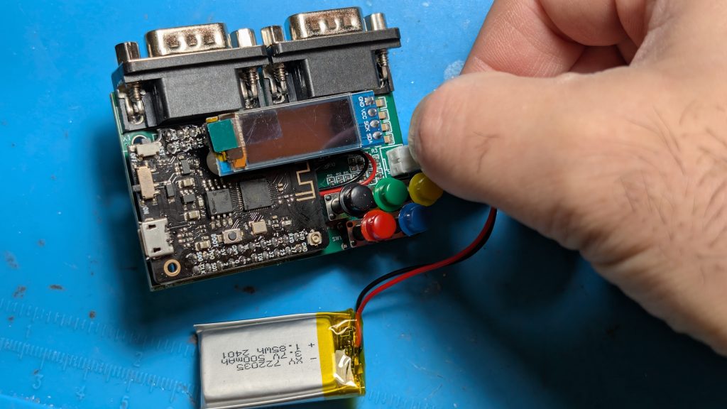
Place the screen on and connect the battery.
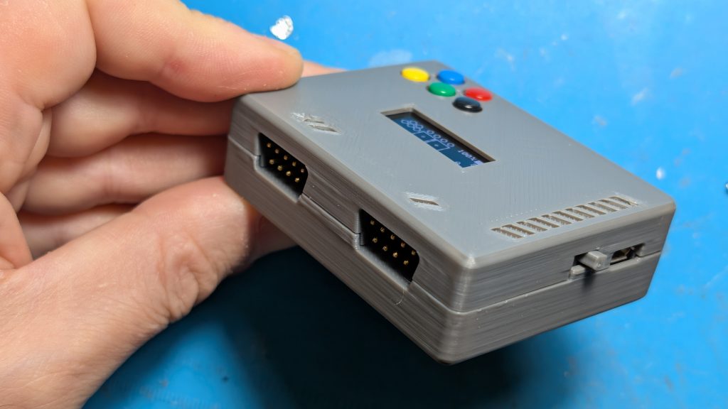
Turn it on with the small on/off toggle switch on the side.
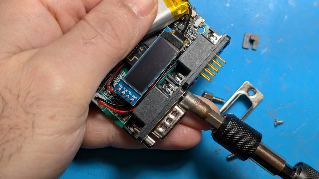
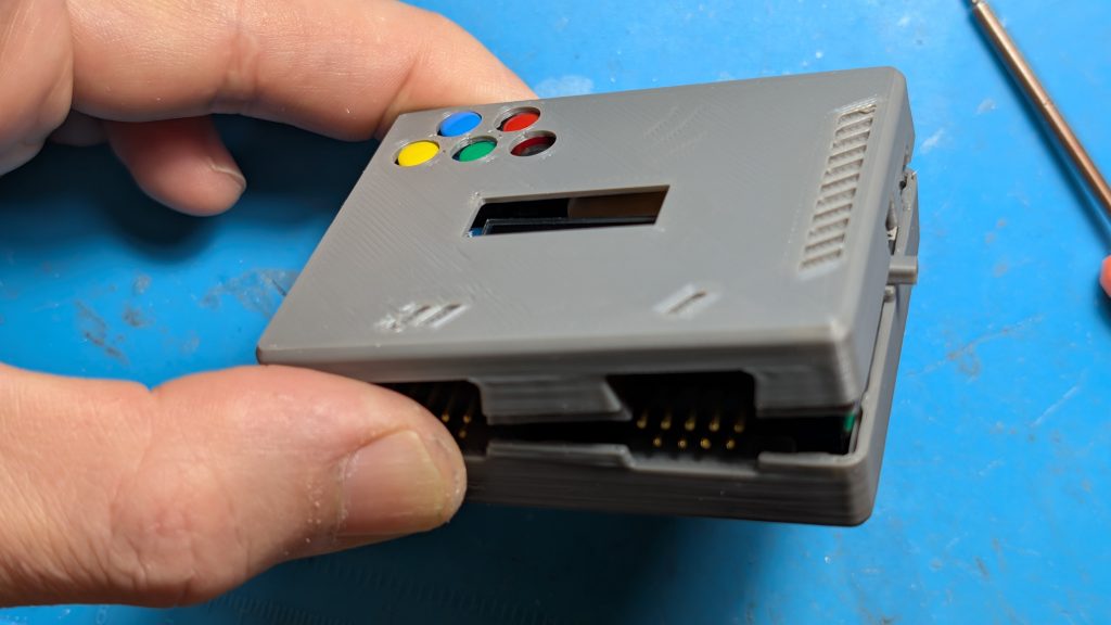
You are done, unless you want to put the unit in a 3D printed case…


Leave a comment
Your email address will not be published. Required fields are marked *