
Analog to Digital conversion with RC circuit in microcontroller projects.
If you were to take the knob or dial off of an electronic device, you might find a potentiometer underneath it. A potentiometer is a variable resistor, and the kind shown below changes resistance as the knob turns. This particular one has a resistance range from 0 ohms to 10,000 ohms.

RC circuit use combination of a resistor (R) and a capacitor (C) to control charge rate of a capacitor. One of the applications of RC circuits is to use a potentiometer as the resistor (R) and this allows you to control how it takes to charge the capacitor (C). The higher the resistance, the longer it takes for the capacitor to charge.

These two components together form an RC (resistor-capacitor) circuit. When the switch is turned on, the capacitor begins to charge. The charge rate always follows the following standard RC charging curve.

The amount of time it takes for charging the capacitor to 63.2% can be calculated using the formula T = R*C in seconds. So for above T = R*C = 100k x 22uF = 2.2 Seconds to get to the 1T line.
TTL circuits on micro controllers typically have a threshold voltage of 1.6V before they recognize an input as HIGH.
So what you can do is connect a digital port to the + side of the capacitor (Vc). Set the port to INPUT mode and force it to LOW. This will discharge the capacitor and immediately the capacitor will begin to charge. Now in a tight loop, just count up from zero and read the PIN till it goas high.
pinMode(pinVC, INPUT);
digitalWrite(A0, LOW); // this will discharge the capacitor
Int i=0; While (! digitalread(PinVC)) { i++; }
The value of i will vary based on how you turn the knob!
To calculate how long it takes for the capacitor to get to a certain voltage you can use the following: t = -ln((Vs-Vc)/Vs)R*C
ln mean natural log or log base e, Vs is the supply voltage, and Vc is the voltage across capacitor
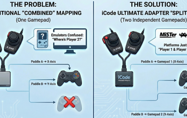
For example, an Atari Paddle uses a 1 Meg ohm resistor. Say we wanted to read the paddles at least 30 times per second using a 5v microcontroller board. What value of capacitor should we use? If you use a 1 Meg Ohm Pot and a 5v board with 1.6 volts being the TTL threshold voltage, a capacitor of 0.068uF, it will take 26.23ms for the pin to go high at the max pot value. – ln((5-1.6)/5)*1000000*0.000000068 = 26.23ms This means you can read it ~38 times per second (1000 / 26.23). Since NTSC frame rate is about 30 frames per second, this will allow you to read it at least once per frame! This is probably why Atari hardware uses a 0.068uF capacitor in its RC circuit

Leave a comment
Your email address will not be published. Required fields are marked *