Call us 24/7+1 (571) 339-9155
FREE DELIVERY on all orders over $20

How to Set Up Atari Joysticks & Paddles in RetroArch with the Duo Ultimate H1 USB Adapter (Windows)

Setup Guide

A friendly, step-by-step walkthrough for Windows. By the end, your classic Atari joysticks and paddles will play smoothly in RetroArch — including up to four paddle players.

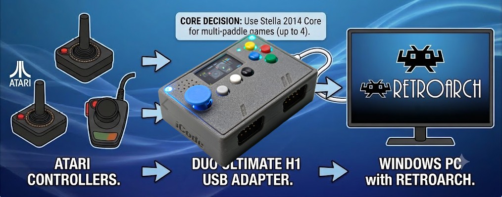
The Duo Ultimate H1 is a USB adapter that lets you plug real Atari joysticks and paddles into your PC. RetroArch can then use them to play Atari 2600 games. This guide covers the whole process from plugging in to saving your settings, and it’s written for beginners — no prior RetroArch experience needed.

What you’ll need

  • A Windows PC with RetroArch installed (this guide uses version 1.21.0)
  • The Duo Ultimate H1 USB adapter
  • Your Atari joystick(s) and/or paddle(s)
  • The Stella 2014 core installed in RetroArch (see the note below)
  • Your Atari 2600 game files
Important: use the right core for paddles

For paddles, use the Stella 2014 core — not the regular Stella core. Stella 2014 supports full 4-player paddles. The regular Stella core currently has a bug that limits it to 1-player paddles.

Adapter settings

Leave the Duo Ultimate on its default mode: Stick + Paddles, Left Analog. Since we’re playing Atari games with Atari paddles, keep any mouse option on standby or off.

1. Connect the adapter (order matters)

The Duo Ultimate is detected most reliably if you start it in this order:

  1. Start RetroArch first, while the Duo Ultimate is still powered off.
  2. Now power on the Duo Ultimate. RetroArch should detect it automatically. You’ll usually see a couple of small notifications float up from the bottom of the screen — typically “PS3 Controller 1” and “PS3 Controller 2.” Those are the adapter’s two ports (two players), and it’s a good sign.

Don’t worry if you don’t see the pop-ups — we’ll verify everything by hand in the next steps.

Why “PS3 Controller”? Windows recognizes the Duo Ultimate as a PS3-style gamepad — that’s just its default emulation mode. It behaves like an ordinary game controller plugged into your PC.

2. Set up Player 1 (Port 1) in RetroArch

First we’ll tell RetroArch which physical controller is Player 1 and teach it which buttons do what.

Open the input binds

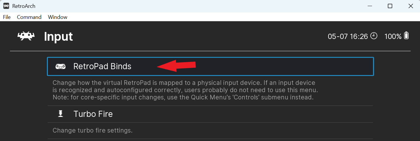
From the RetroArch main menu, go to the top-level Settings menu → InputRetroPad Binds.

RetroArch Input menu with RetroPad Binds highlighted
Settings → Input → RetroPad Binds.

Inside RetroPad Binds you’ll see Port 1 Controls, Port 2 Controls, and so on. Each port is a player: Port 1 = Player 1, Port 2 = Player 2.

Point Port 1 at the adapter, and keep it analog

Open Port 1 Controls and check two settings near the top:

  • Device Index should read PS3 Controller (1). It’s usually set automatically. If it isn’t, press Enter on Device Index and pick PS3 Controller (1) from the list.
  • Analog to Digital Type should be None. This keeps your input as true analog — essential for paddles, which need smooth, continuous left-and-right motion rather than being chopped into digital left/right.
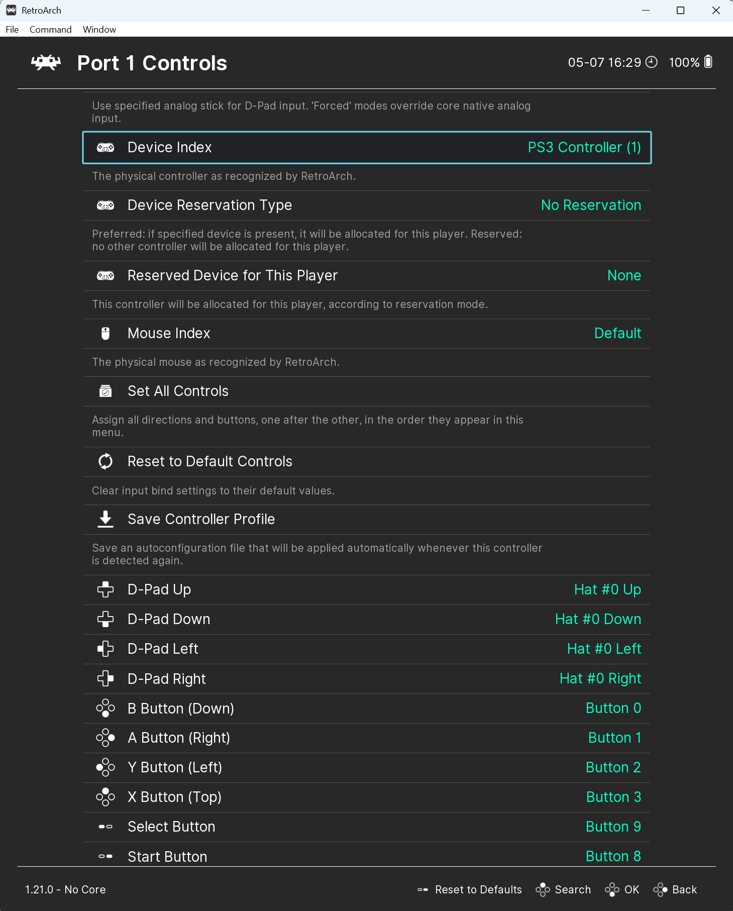
Port 1 Controls showing Device Index set to PS3 Controller (1)
Port 1 → Device Index set to PS3 Controller (1).

Map the buttons

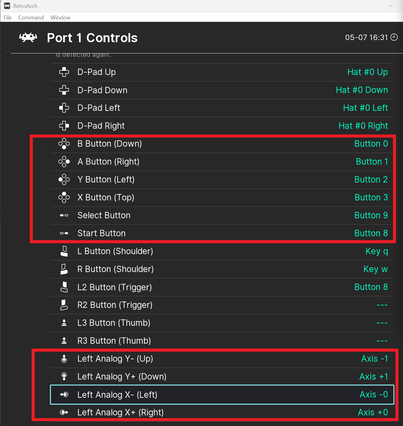
Scroll down past Device Index to the list of buttons (D-Pad Up, B Button, and so on). Leave the D-Pad on its defaults. To set a button, select it and press Enter — RetroArch gives you about 2 seconds to press the button you want before it times out, so press and hold the button on the Duo until it registers.

Map these six:

RetroArch button Press & hold on the Duo Should show
B Button Red Button 0
A Button Green Button 1
Y Button Blue Button 2
X Button Yellow Button 3
Select White Button 9
Start Black Button 8
Heads up: A and B can look swapped

On some units the red and green buttons appear reversed. The reliable rule is to match by button number: B Button = Button 0 and A Button = Button 1. If your colors don’t match the table, trust the button number shown on screen.

Map the joystick directions

Keep scrolling to the Left Analog entries and move your joystick in each direction to bind it. These come out as axes:

RetroArch bind Move joystick Should show
Left Analog Y- (Up) Up Axis -1
Left Analog Y+ (Down) Down Axis +1
Left Analog X- (Left) Left Axis -0
Left Analog X+ (Right) Right Axis +0
Port 1 Controls showing button numbers and Left Analog axis assignments
Port 1 buttons (top box) and the Left Analog axes for joystick directions (bottom box).

3. Set up Player 2 (Port 2)

Set up Port 2 Controls the same way you did Port 1, with one difference:

  • Device Index must be PS3 Controller (2) — the number (2), not (1).
  • Analog to Digital Type = None, same as before.
  • Map the buttons and joystick directions just like Port 1 — except you can skip Select and Start. On the Duo Ultimate, the Start and Select buttons live on Port 1 only, so they don’t matter for Port 2.

Make sure Port 1 and Port 2 use different device indexes. If both are set to PS3 Controller (1), the two players share one physical port and it won’t work.

4. Turn on paddles in Stella 2014

The steps above cover joysticks. Paddles need one more layer of setup inside a game, using the Stella 2014 core.

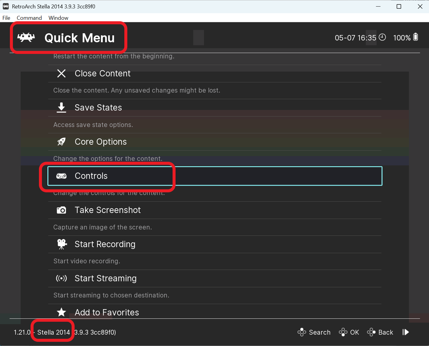
  1. Load an Atari 2600 game (for example, Breakout) using the Stella 2014 core, then press F1 to open the RetroArch Quick Menu.
  2. Choose Controls.
RetroArch Quick Menu with Controls highlighted, Stella 2014 core
In-game: press F1Controls. (Note “Stella 2014” at the bottom.)

Port 1 → Players 1 & 2

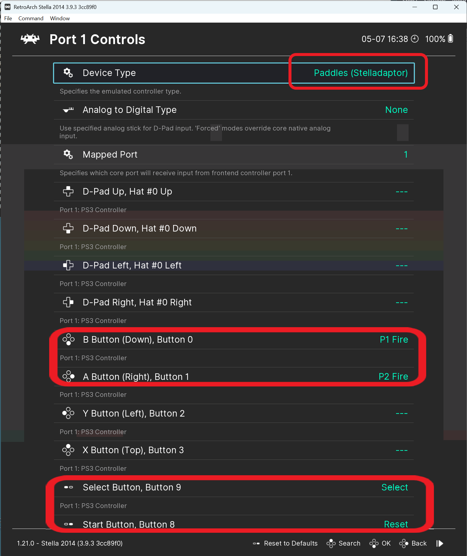
Open Port 1 Controls and set Device Type to Paddles (Stelladaptor). RetroArch relabels the controls to paddle functions. Confirm:

  • B ButtonP1 Fire
  • A ButtonP2 Fire
Port 1 Controls with Device Type Paddles (Stelladaptor), B Button as P1 Fire and A Button as P2 Fire
Port 1 → Device Type Paddles (Stelladaptor); B = P1 Fire, A = P2 Fire.

The paddle dials (the twist knobs) come from the Left Analog stick automatically: the X axis is Player 1’s paddle and the Y axis is Player 2’s paddle. So Port 1 alone gives you two paddle players.
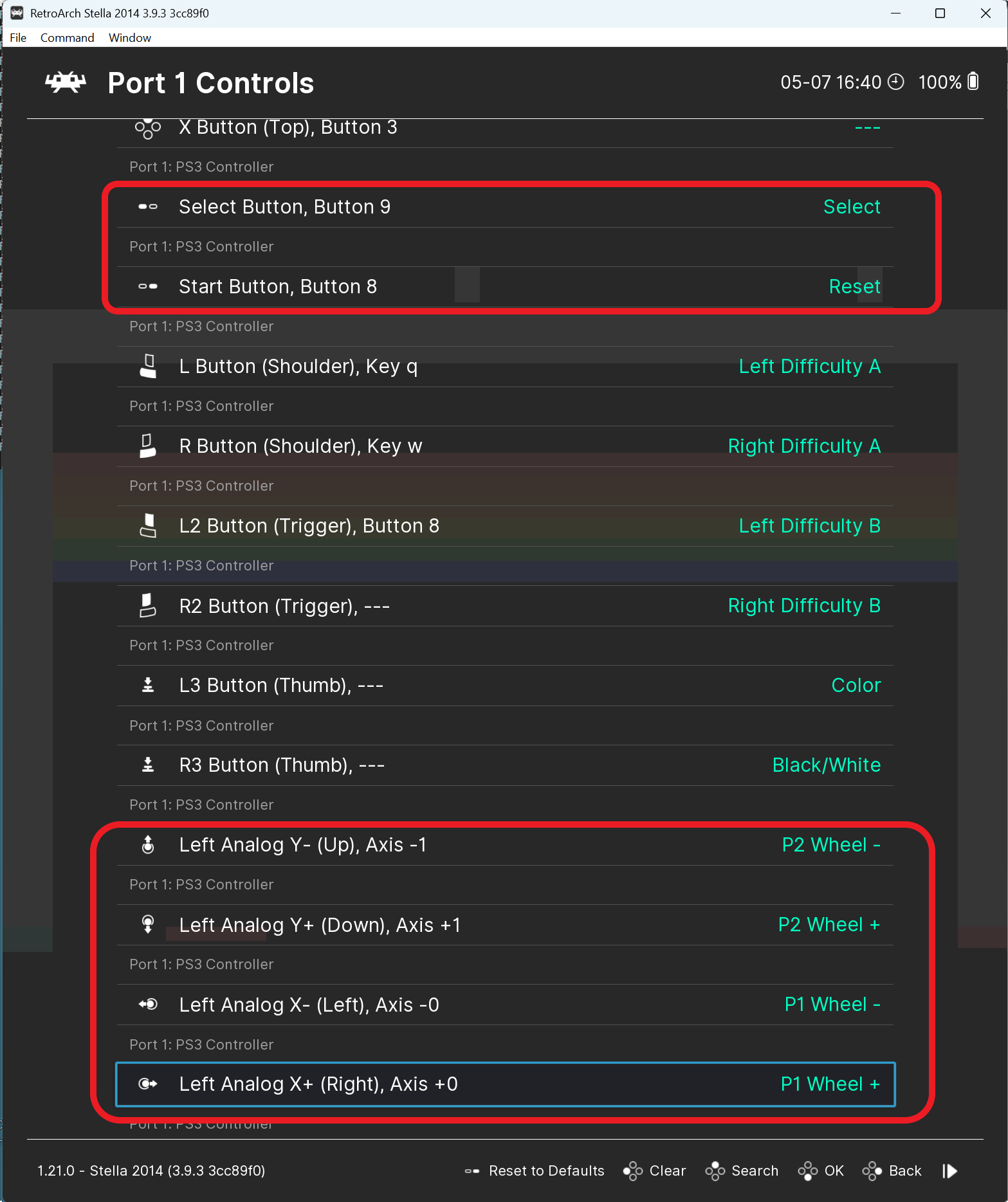
Port 1 Left Analog axes mapped to P1 Wheel and P2 Wheel
Left Analog X = P1 paddle wheel, Y = P2 paddle wheel.

Port 2 → Players 3 & 4

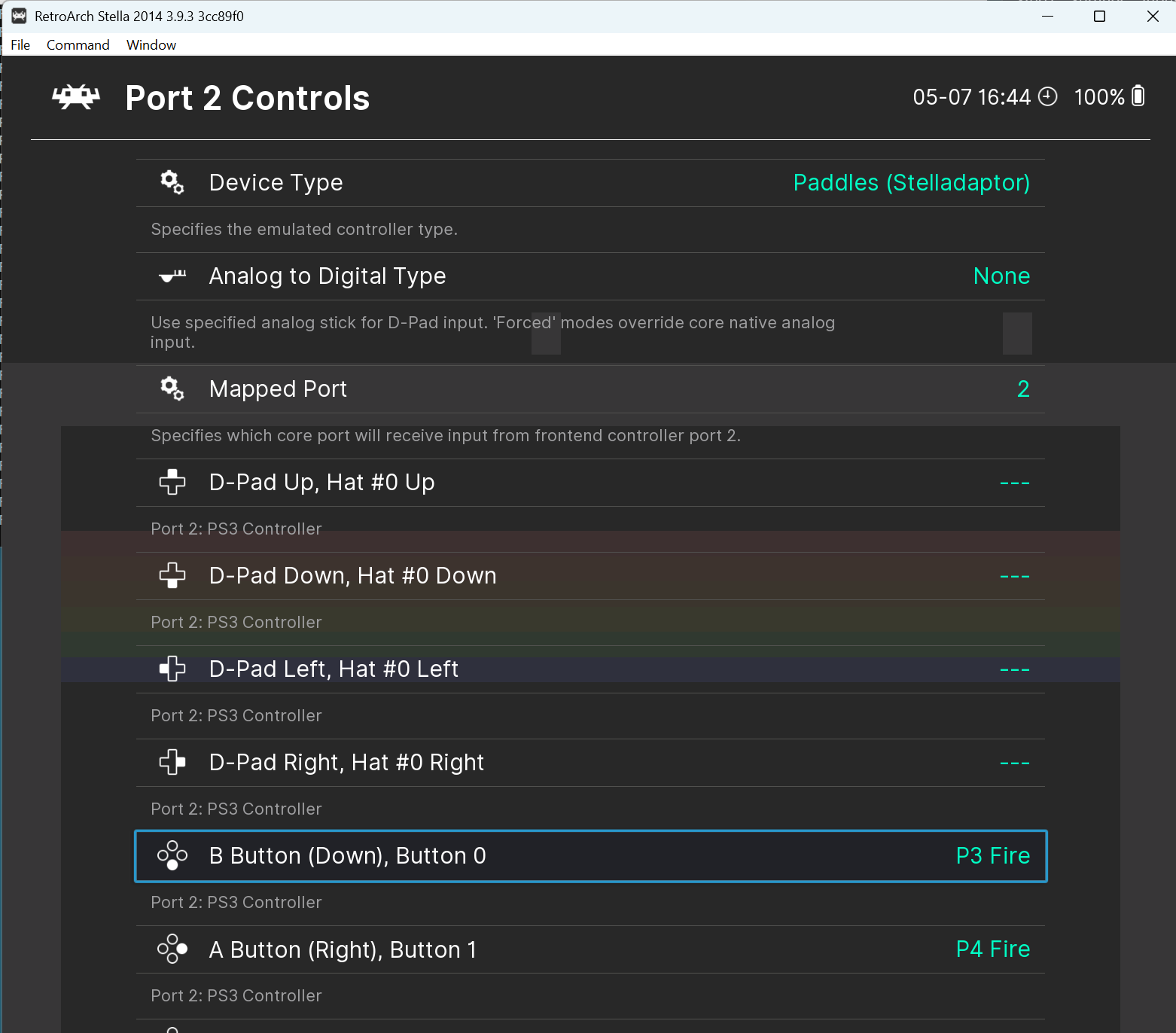
For four-player paddle games, open Port 2 Controls, set Device Type to Paddles (Stelladaptor), and confirm:

  • B ButtonP3 Fire
  • A ButtonP4 Fire
Port 2 Controls with Paddles device type, B Button as P3 Fire and A Button as P4 Fire
Port 2 → Device Type Paddles (Stelladaptor); B = P3 Fire, A = P4 Fire.

As with Port 1, the paddle dials come from the analog axes: X = Player 3, Y = Player 4.
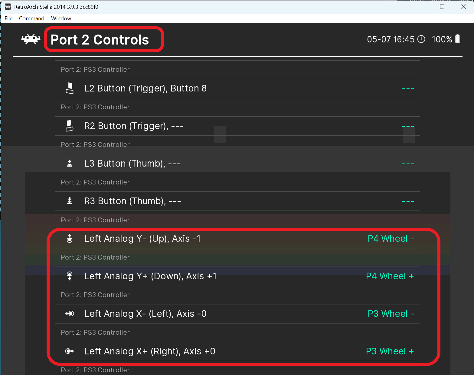
Port 2 Left Analog axes mapped to P3 Wheel and P4 Wheel
Left Analog X = P3 paddle wheel, Y = P4 paddle wheel.

5. Save your settings so you only do this once

To avoid redoing the paddle setup for every game, save it as a core remap. Still in the Controls menu, choose Manage Remap Files.
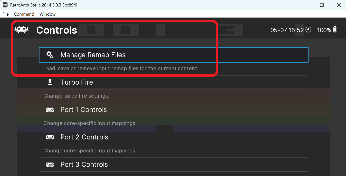
Controls menu with Manage Remap Files highlighted
Controls → Manage Remap Files.

Then choose Save Core Remap File. This applies your paddle setup to every game you load with the Stella 2014 core. (If you’d rather limit it to one game or one folder, the Save Game Remap and Save Content Directory Remap options are right there too.)
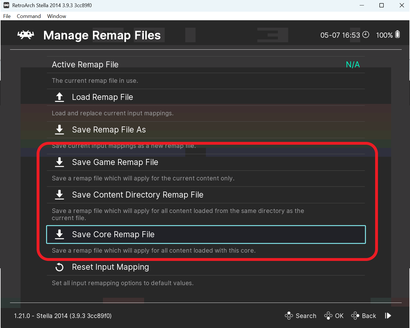
Manage Remap Files with Save Core Remap File highlighted
Choose Save Core Remap File to apply this to all Stella 2014 games.

6. Troubleshooting & tips

  • Nothing detected when you power on the Duo? Make sure you started RetroArch first, then powered the adapter. Try toggling it off and on.
  • Both players move together / Player 2 does nothing? Check that Port 1 = PS3 Controller (1) and Port 2 = PS3 Controller (2) — not both on (1).
  • A and B feel reversed? The colors can differ between units. Map by button number: B = Button 0, A = Button 1.
  • Paddles jump around or only one player works? Confirm you’re on the Stella 2014 core (not regular Stella), that Device Type = Paddles (Stelladaptor), and that Analog to Digital Type = None.
  • Using paddles? Keep any mouse device on standby/off so it doesn’t interfere.

7. Quick reference tables

Port 1 button binds (Settings → Input → RetroPad Binds)

RetroArch button Value Color (may vary)
B Button Button 0 Red
A Button Button 1 Green
Y Button Button 2 Blue
X Button Button 3 Yellow
Select Button 9 White
Start Button 8 Black
Left Analog Y- / Y+ (Up/Down) Axis -1 / Axis +1 Joystick
Left Analog X- / X+ (Left/Right) Axis -0 / Axis +0 Joystick

Paddle mapping (Stella 2014, Device Type = Paddles)

Frontend port Fire buttons Paddle dials (Left Analog) Players
Port 1 B = P1 Fire, A = P2 Fire X = P1, Y = P2 Players 1 & 2
Port 2 B = P3 Fire, A = P4 Fire X = P3, Y = P4 Players 3 & 4

That’s it — your Atari joysticks and paddles should now play beautifully in RetroArch. Load up Breakout or Warlords and enjoy the classics the way they were meant to be played.
Setup verified on RetroArch 1.21.0 (Windows) with the Stella 2014 core (3.9.3) and the Duo Ultimate H1 USB adapter.

How to Set Up 4-Player Paddles on MiSTer FPGA with the iCode Duo Ultimate

⏱️ Time
10 minutes
🎯 Difficulty
Beginner-friendly
🕹️ Hardware
iCode Duo Ultimate
🎮 Game
Warlords (Atari 7800 core)

Want to play Warlords four-player on a MiSTer FPGA? The iCode Duo Ultimate reads both paddles on each of its two DB9 ports and presents them to MiSTer as two USB gamepads — giving you all four paddles. This quick-start walks you through the exact device and core settings, including the one button-mapping trick that trips most people up.


What You’ll Need

  • iCode Duo Ultimate adapter
  • Two pairs of Atari paddles (CX-30) — one pair in Port 1, one pair in Port 2
  • A MiSTer FPGA with the Atari 7800 core installed
  • A USB keyboard connected to the MiSTer (for the menus)

Step 1 — Configure the Duo Ultimate

On the adapter, set the following (save to a preset so it’s one-tap next time):

  1. Emulation Mode → Classic. This is the most reliable mode for MiSTer — it presents a controller identity MiSTer maps correctly out of the box.
  2. Console → Atari, and set each port’s device to Paddles (or Stick+Paddles for auto-detect).
  3. Dual Paddles → Combined. Each port becomes one USB gamepad carrying its two paddles.
  4. Function → Left Analog. This routes the paddles onto the left-stick X and Y axes — the axes MiSTer’s paddle support reads. (On the right stick or triggers, MiSTer ignores them.)

Plug the Duo into the MiSTer’s USB port. You now have two gamepads: Gamepad 1 = Port 1’s paddles (X = Paddle A, Y = Paddle B), Gamepad 2 = Port 2’s paddles (X = Paddle A, Y = Paddle B).

Reading the display: The Duo shows a yellow dot (Paddle A / 1A) and a blue dot (Paddle B / 1B) that track each paddle’s live position. Keep both paddles centered at the 12 o’clock position whenever you’re not actively turning one — if a paddle drifts off-center, both the button mapping and the player assignment become much harder. Re-center to 12 o’clock between every step.

Step 2 — Configure the Atari 7800 Core

Load the Atari 7800 core, open the OSD (F12), and go to the Peripherals menu:

  1. Port1 Input → Paddle
  2. Port2 Input → Paddle
  3. Allow Multi Paddles → Yes (this lets each gamepad supply two paddles — one on X, one on Y)

Then run a Hard Reset (or reload the game). This is required — it clears any previous paddle assignments so the next steps start clean.


Step 3 — Map the Buttons (the important part)

Directions and paddle buttons are defined inside the core’s own setup — and the directions are mapped by turning the paddles, not by pressing anything, because in Combined mode each paddle is a stick axis. Keep both paddles at 12 o’clock except when a prompt asks you to move one, and always return to 12 o’clock before the next prompt.

  1. In the Atari 7800 core OSD, open “Define Atari 7800 buttons.”
  2. RIGHT: turn Paddle 1A (yellow dot) clockwise, then back to 12 o’clock.
  3. LEFT: turn Paddle 1A (yellow dot) counter-clockwise, then back to 12.
  4. UP: turn Paddle 1B (blue dot) counter-clockwise, then back to 12.
  5. DOWN: turn Paddle 1B (blue dot) clockwise, then back to 12.
  6. FIRE 1 — skip it (press Space on the keyboard, or the User button).
  7. FIRE 2: press the Paddle 1B fire button.
  8. Select and Start / Reset: press the black and white buttons on the Duo.
  9. Skip any other prompts you don’t need.
  10. At the very end it asks for PADDLE BUTTON — press the Paddle 1A fire button.
Critical: Do not map FIRE 1. If FIRE 1 is mapped, the core will not let you assign the Paddle Button, and your paddle triggers won’t work. Skipping FIRE 1 is what frees up the Paddle Button slot.

Step 4 — Assign the Four Paddles

With both ports set to Paddle, Multi Paddles on, and the core freshly reset, load Warlords and assign each paddle by turning it fully to its stop, then back to 12 o’clock. Watch for the on-screen “Assigned” confirmation after each one, and do them in this order:

  1. Turn Port 1, Paddle A fully → Paddle 1A Assigned (Player 1)
  2. Turn Port 1, Paddle B fully → Paddle 1B Assigned (Player 2)
  3. Turn Port 2, Paddle A fully → Paddle 2A Assigned (Player 3)
  4. Turn Port 2, Paddle B fully → Paddle 2B Assigned (Player 4)

Order matters — the paddles fill the four slots in sequence, so assign them one at a time and wait for each confirmation. Keeping the other paddles centered at 12 o’clock while you do this prevents the wrong paddle from grabbing a slot. That’s it: four players, four paddles.


Quick Reference

  • Emulation Mode: Classic
  • Dual Paddles: Combined  |  Function: Left Analog
  • Core (Peripherals): Port1 = Paddle, Port2 = Paddle, Allow Multi Paddles = Yes
  • Display dots: yellow = Paddle 1A, blue = Paddle 1B — keep paddles at 12 o’clock unless actively turning one
  • Buttons (Define Atari 7800 buttons): directions = turn the paddles (Right/Left = 1A yellow CW/CCW, Up/Down = 1B blue CCW/CW, each back to 12); skip Fire 1; Fire 2 = Paddle 1B button; Select/Start = Duo black & white buttons; Paddle Button = Paddle 1A button
  • Assign order: Port 1 A → Port 1 B → Port 2 A → Port 2 B (turn each fully, wait for confirmation)
  • Always Hard Reset the core after changing paddle settings.

Related


Atari Dual Paddles as Independent Gamepads? Here’s How the iCode Ultimate Adapter Has the Answer.

If you’ve ever tried to get two-player Atari paddle games working on modern hardware, you know the frustration. Maybe it’s MiSTer FPGA where Player 2 is completely invisible. Maybe it’s RetroArch where you spent an hour buried in input configuration menus trying to map the Y axis to a second virtual player. Maybe it’s a standalone emulator that simply doesn’t support two paddles on one gamepad at all.

Your paddles are fine. Your adapter is fine. The problem is how USB adapters have traditionally reported paddle data — and it creates headaches on virtually every platform. Some emulators can work around it with enough manual configuration. Most can’t. And even when they can, the process is error-prone, poorly documented, and different for every emulator. Until now, nobody has solved this at the adapter level where it belongs.

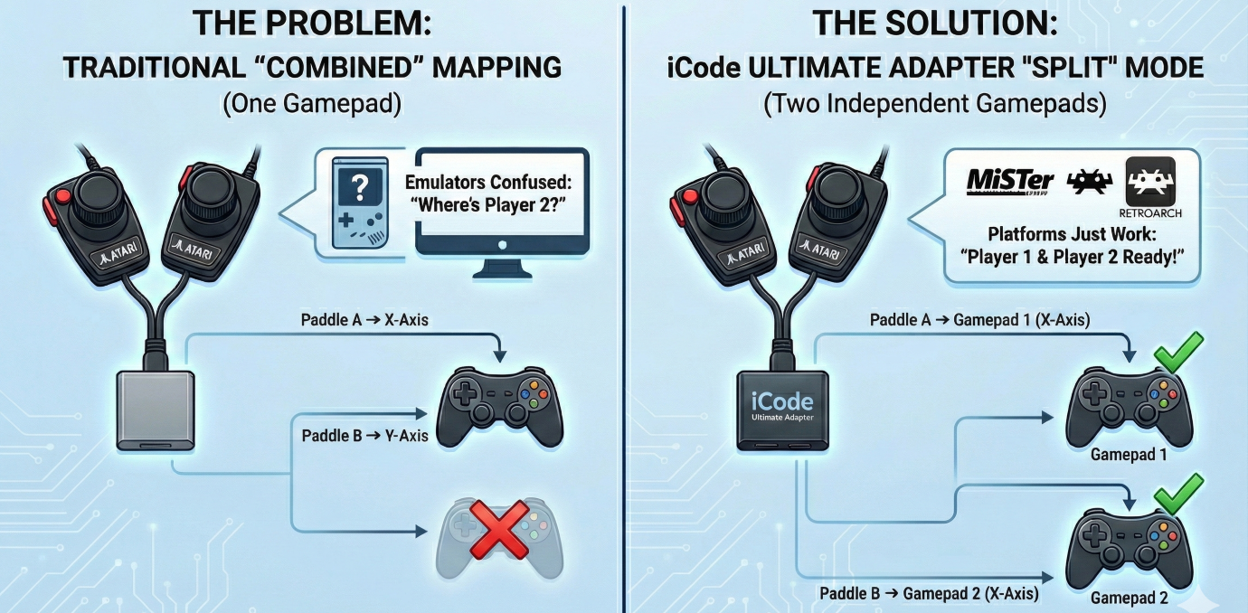
The Problem: Two Paddles, One Gamepad

Atari paddles come in pairs. A single DE-9 connector carries two paddles — each with its own potentiometer and fire button — sharing the same port. The original 2600 handled this natively because it was designed around this exact hardware. Paddle A and Paddle B were simply two separate inputs on the same controller port.

When USB adapters came along, they had to translate this into something a modern computer could understand. The standard approach became: map Paddle A to the X axis of a gamepad, Paddle B to the Y axis, and the two fire buttons to buttons 0 and 1. One physical port, one USB gamepad, two axes. Simple, clean, and it works — for emulators that know how to read it.

Even emulators that theoretically support this — like RetroArch or Stella — aren’t straightforward. You might get lucky after spending hours digging through input configuration menus, remapping axes, and praying it sticks between sessions. And then you update the emulator or switch cores and get to do it all over again. The reality is that no platform handles the “two paddles on one gamepad” approach gracefully.

Why Most Platforms Struggle with Dual Paddles

The root of the problem is simple: most platforms expect one gamepad per player.

MiSTer FPGA’s Atari cores expect Player 1 on gamepad 1’s X axis and Player 2 on gamepad 2’s X axis. It never looks at the Y axis for a second paddle — it looks for a second USB device entirely. Player 2 is completely invisible.

But MiSTer is just the most obvious example. The same issue appears everywhere:

  • RetroArch can technically handle it, but you have to manually configure input remapping to bind the Y axis of gamepad 1 to Player 2’s paddle input. The process is buried in nested menus, varies by core, and resets if you change controllers. Most users never get it working.
  • RetroPie inherits RetroArch’s complexity and adds its own layer of input configuration on top. Getting dual paddles working often means editing config files by hand.
  • Standalone emulators like Atari800 or MAME each have their own input mapping systems, each with different assumptions about how paddles should arrive over USB. What works in one breaks in another.
  • FPGA platforms beyond MiSTer — including Analogue devices and other retro FPGA projects — generally follow the one-gamepad-per-player model.

The common thread is that every platform requires you to solve the same problem from the receiving end, with platform-specific configuration that’s fragile, frustrating, and easy to get wrong. Change your adapter, update your emulator, or switch platforms, and you’re starting over.

The real fix belongs at the source — in the adapter itself.

Our Solution: Split Mode

The iCode Duo Ultimate Adapter now includes a Dual Paddles setting with two modes: Combined and Split.

Combined is the traditional behavior. Both paddles from a port map to the same USB gamepad — Paddle A on X, Paddle B on Y, fire buttons on buttons 0 and 1. This is the default and may work on some emulators with manual input configuration — if you have the patience.

Split solves the compatibility problem at the source. When activated, the adapter remaps the paddle data across both USB gamepads:

Split Mode — Single Pair of Paddles
Physical Source USB Output Player
Port 0 Paddle A Gamepad 1, X axis + Btn 0 Player 1
Port 0 Paddle B Gamepad 2, X axis + Btn 0 Player 2

Every platform — MiSTer, RetroArch, RetroPie, MAME, standalone emulators, FPGA devices — now sees exactly what it expects: two independent controllers, each with a paddle on the X axis. Player 1 and Player 2 just work. No input remapping, no config file editing, no per-emulator workarounds. Flip one setting on the adapter and you’re done.

What About Four Paddles?

This is where it gets interesting. If you have paddles connected to both ports — the full four-paddle setup for games like Warlords — Split mode handles that too.

Split Mode — Four Paddles (Two Pairs)
Physical Source USB Output Player
Port 0 Paddle A Gamepad 1, X axis + Btn 0 Player 1
Port 1 Paddle A Gamepad 1, Y axis + Btn 1 Player 3
Port 0 Paddle B Gamepad 2, X axis + Btn 0 Player 2
Port 1 Paddle B Gamepad 2, Y axis + Btn 1 Player 4

Gamepad 1 carries both “A” paddles, Gamepad 2 carries both “B” paddles. Platforms that expect one paddle per gamepad pick up Players 1 and 2 from the X axes automatically, and emulators that support four paddles can read all four from the two gamepads.

The adapter intelligently manages this — Split mode only activates when both ports actually have paddles available. If you’ve got a joystick on Port 1 and paddles on Port 0, the adapter stays in Combined mode regardless of the setting. No conflicts, no confusion.

Settings Follow the Destination

One design decision we’re particularly happy with is how settings work in Split mode. Each USB gamepad’s paddle behavior — resolution, jitter control, button mapping — is controlled by the port settings for that gamepad’s slot. Gamepad 1 uses Port 1’s settings, Gamepad 2 uses Port 2’s settings.

This means you can configure each player’s paddle experience independently through the menu, and the settings make intuitive sense: what you configure under “Port 1” always controls what comes out of USB Gamepad 1, regardless of which physical paddle is being mapped there.

Stick + Paddles Still Works

For Stick+Paddles mode, Split works seamlessly alongside digital joystick input. The joystick from Port 0 routes to Gamepad 1, and the joystick from Port 1 routes to Gamepad 2 — exactly where you’d expect them. The paddle split only affects the analog data and fire buttons, so your digital controls remain unchanged.

How to Enable It

Quick Setup

1. Navigate to Settings
2. Find Dual Paddles (visible when Console is set to Atari)
3. Select Split

That’s it. No reboot required, no firmware changes, and — most importantly — no configuration needed on the emulator side. No input remapping in RetroArch, no config file editing in RetroPie, no per-core setup on MiSTer. The adapter sends the data the right way from the start, so every platform just works.

The Bigger Picture

This is part of our ongoing effort to make the iCode Duo Ultimate Adapter work everywhere, not just in the most common setups. Paddle support has always been a pain point for the retro gaming community — between jitter issues, calibration problems, and now platform compatibility — and we’ve been systematically knocking down every barrier.

Combined with our four-stage jitter elimination pipeline, auto-calibration, and adjustable resolution control, Split mode means Atari paddles finally work the way they should on every platform. Whether you’re playing Breakout on RetroArch or Warlords on MiSTer, the iCode Ultimate Adapter handles it — and your paddles just feel right.

Demystifying Atari Paddle Jitter: How the iCode Ultimate Adapter Delivers the Smoothest Paddle Experience

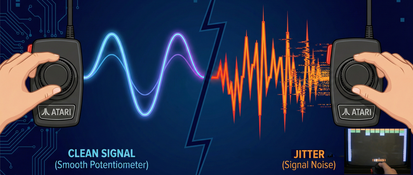
If you’ve ever plugged vintage Atari paddles into a USB adapter and watched your on-screen paddle twitch and dance while sitting perfectly still, you’ve experienced paddle jitter. It’s the number one complaint from retro gamers trying to play Breakout, Kaboom!, or Warlords on modern hardware. But what actually causes it — and can it be fixed?

We spent months studying the problem at the hardware level, and built a multi-stage signal processing pipeline into the iCode Ultimate Adapter that eliminates jitter while preserving the instant, zero-lag response that makes paddle games feel right. Here’s how it works.

The Root Cause: RC Timing and Analog Noise

Atari paddles aren’t digital devices. Each paddle contains a 1-megaohm potentiometer — a variable resistor that changes based on the knob’s position. The original Atari 2600 read this resistance using an RC (resistor-capacitor) timing circuit: charge a capacitor through the paddle’s resistance, and measure how long it takes. High resistance (knob turned one way) means a long charge time; low resistance (the other way) means a short one.

Modern adapters replicate this same RC timing approach. The microcontroller discharges a capacitor, then counts how many microseconds it takes to charge back up through the paddle. That count — the RC time — becomes the paddle’s position value.

The problem? Analog circuits are inherently noisy. The capacitor’s charge time fluctuates by a few counts every single read. Temperature, component tolerances, electrical interference from the USB bus, and even the age of the potentiometer all contribute. On a 40-year-old paddle with worn carbon traces, the noise can be significant. And unlike a digital joystick where you’re either on or off, even a 1–2 count fluctuation in RC time translates to visible on-screen jitter.

Dirty or worn paddles make it worse. A momentary loss of contact — common with oxidized wiper contacts — causes the RC time to spike wildly before snapping back. Traditional adapters faithfully pass these glitches straight through to the game, resulting in the paddle teleporting across the screen and back in a single frame.

Our Approach: A Four-Stage Signal Pipeline

Rather than applying a single heavy-handed filter that kills responsiveness, we built a pipeline of four lightweight stages. Each one targets a specific type of noise, and together they produce a clean, stable signal with effectively zero added latency for real paddle movement.

Raw
RC Reading
Stage 1
Spike Reject
>50% = drop
Stage 2
Moving Avg
4-sample
Stage 3
Hysteresis
deadband
Stage 4
Auto-Cal
0–254 map
Output
Clean Signal

Stage 1: Spike Rejection

This is our defense against dirty contacts. If a reading jumps more than 50% from the previous value in a single frame, we throw it away entirely. Real paddle movement is smooth and continuous — even the fastest flick of the wrist produces a gradual ramp across multiple readings. A spike from a dirty wiper contact, on the other hand, appears as an instantaneous jump with no ramp.

By rejecting these outliers at the source, we prevent them from corrupting everything downstream. The paddle simply holds its last known good position for that frame, and resumes tracking normally on the very next read. In practice, this is completely invisible — you can’t perceive a single skipped frame at 1000+ reads per second.

Stage 2: Moving Average

To understand why this works so well, we need to talk about capacitors.

The original Atari 2600 used a 68nF capacitor in its RC timing circuit. Combined with the paddle’s 1-megaohm potentiometer, this meant each read cycle took long enough that the console could only squeeze in a single scan per frame — and at 60 frames per second, that was it. One reading, one chance, take it or leave it. Atari’s engineers knew this was noisy, which is partly why they clipped the paddle range so aggressively. Less range meant less time per scan, which helped keep things within the tight timing budget of the TIA chip.

When Atari moved to their 8-bit computer line (the 400/800 series), they switched to a 47nF capacitor — smaller, faster charge times, slightly better performance. But the fundamental constraint remained: one scan per frame, no room for averaging.

Platform Capacitor CPU Speed Scans/Frame
Atari 2600 68nF 1.19 MHz 1
Atari 400/800 47nF 1.79 MHz 1
iCode Ultimate 22nF 150 MHz 4+

The iCode Ultimate Adapter breaks this limitation entirely. We use a 22nF capacitor — roughly a third the size of the original 2600’s. Combined with the RP2350 microcontroller running at 150MHz (compared to the 2600’s 1.19MHz), each RC scan completes in a fraction of the time. Where the Atari could barely fit one scan into a frame, we can comfortably perform four complete scans in the same window — with time to spare and zero additional lag.

This is what makes our 4-sample moving average practical. Every output value is the average of four independent RC readings taken in rapid succession. Random analog noise — those 1–2 count fluctuations from electrical interference, temperature drift, and component variation — cancels itself out across the four samples. Real paddle movement, which is consistent across all four reads, passes through cleanly.

The result is a noise floor that’s effectively halved compared to a single-scan approach, with no perceptible latency added. Four samples at our scan rate span just a few milliseconds — far below the threshold of human perception, but enough to tame the analog noise that plagues every other adapter on the market.

Stage 3: Hysteresis (Jitter Control)

This is where the remaining low-frequency drift gets eliminated. Even after averaging, the signal might wobble by a few counts when the paddle is sitting still. Hysteresis solves this by requiring the value to change by more than a configurable threshold before we update the output.

Think of it like a deadband around the current position. If the paddle’s stable RC time is 1000 and the threshold is 8, readings between 992 and 1008 are ignored. The moment you actually turn the knob and the value hits 1009, the new position passes through immediately — no delay, no lag. It only suppresses the idle wobble.

Jitter Control Settings
None — No filtering (raw signal)  ·  Very Low — Threshold of 4  ·  Low — Threshold of 8 (default)  ·  Medium — Threshold of 12  ·  High — Threshold of 16  ·  Very High — Threshold of 20

We expose this as a user-adjustable setting with six levels. Different paddles have different noise characteristics, so what works perfectly for a pristine set of Atari CX30s might need a higher setting for a well-loved pair from 1978. Most users find the Low setting eliminates all visible jitter without affecting gameplay feel.

Stage 4: Auto-Calibration

The final stage maps the filtered RC time to the 0–254 output range that games expect. Rather than using fixed conversion values, we continuously track the actual minimum and maximum RC times seen from each paddle. This means the adapter automatically adjusts to any paddle — regardless of component tolerances, capacitor quality, or manufacturing variations.

The calibration range only grows, never shrinks, so it can’t be corrupted by a single bad reading (those were already caught by spike rejection). If a paddle’s true range is 200 to 1400, that’s the range we map — not some hardcoded guess that might clip your paddle’s travel or leave dead zones at the ends.

Resolution Control: Matching the Atari Feel

There’s one more piece of the puzzle that experienced Atari players appreciate. The original 2600 didn’t use the full range of the potentiometer — it clipped the RC timing at roughly 60–80% of the paddle’s physical travel. This meant you only needed a small wrist movement to cover the entire screen, giving paddles their characteristic snappy, responsive feel.

Our Resolution setting replicates this by controlling how much of the RC timing range maps to full output. At 50%, a small physical movement covers the whole screen — fast and twitchy, just like the original hardware. At 100%, you get the full range for fine-grained precision. The default of 80% matches the feel most players remember from their Atari 2600.

Because this clipping also determines when the RC timing loop can exit early, lower resolution settings actually improve adapter performance — the microcontroller spends less time waiting for each read cycle, leaving more headroom for everything else.

The Result

The combination of these techniques — spike rejection, moving average, hysteresis, and auto-calibration — produces a signal that’s rock-solid when idle and instantly responsive when you move. No jitter, no teleporting, no dead zones, and no perceptible lag.

Every stage is lightweight by design. There’s no heavy digital filtering that mushes your inputs, no prediction algorithms that guess where you’re going, and no frame buffering that adds delay. The pipeline processes each reading in microseconds, and the result is a paddle experience that feels exactly like the original hardware — just without the noise.

Whether you’re threading the needle in Breakout, dodging bombs in Kaboom!, or battling friends in Warlords, the iCode Ultimate Adapter lets vintage Atari paddles perform the way they were always meant to.

Extracting Transparency from Flattened Images

Ever had a semi-transparent graphic — a glass effect, a soft shadow, a wisp of smoke — that got flattened onto a solid background? The transparency data is gone. Or is it?

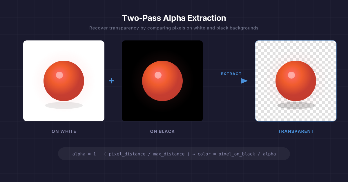
With a surprisingly elegant trick, you can perfectly recover the original transparency by comparing the same image on two different backgrounds. Here’s how.


Quick Start: How to Do It

The whole process is two steps:

1 Prepare two versions of your image. Upload your image to Google Gemini Pro and ask:

Convert this image to a pure solid white #FFFFFF background and keep everything else exactly unchanged

Save the result as white.png. Then, using the white image you just created, ask:

Change the white background to a solid pure black #000000. Keep everything else exactly unchanged

Save the result as black.png.

(It’s important to create black from the white version rather than generating both independently — this ensures the foreground stays perfectly aligned between the two images.)

2 Run the extraction tool. Build the executable (instructions below) and run:

.\extract-alpha.exe white.png black.png output.png

That’s it. output.png is your image with the background removed and full transparency recovered — including semi-transparent edges, shadows, and glass effects that normal background removal tools destroy.


How It Works

The Problem

Let’s say you have a layer in Photoshop, After Effects, or a game engine with semi-transparent pixels. At some point it gets composited onto a solid background and exported as a flat image — a JPEG, a screenshot, a video frame. The alpha channel is gone.

You can’t just threshold or magic-wand your way back, because semi-transparent pixels have blended with the background. A 50% transparent white pixel on a black background looks like medium gray. On a white background, it just looks white. The information about what was foreground and what was transparency has been mixed together.

But here’s the key insight: it mixed differently depending on the background color. And that difference is exactly what we need.

The Trick: Render It Twice

Take your image and render it on two backgrounds:

  • Once on pure white (255, 255, 255)
  • Once on pure black (0, 0, 0)

Now compare each pixel across the two images. The way a pixel changes between the two backgrounds tells you everything about its transparency.

The Math

Think about what happens to a single pixel at different transparency levels.

A fully opaque pixel looks identical on both backgrounds. The background can’t show through, so the color doesn’t change. The distance between the two versions is zero.

A fully transparent pixel takes on the background color completely. On white it appears as (255, 255, 255). On black it appears as (0, 0, 0). The distance between the two versions is the maximum possible — the Euclidean distance between white and black in RGB space:

max_distance = √(255² + 255² + 255²) ≈ 441.67

A semi-transparent pixel falls somewhere in between. The more transparent it is, the more it shifts between backgrounds, and the greater the distance.

This gives us a clean linear relationship:

alpha = 1 − (pixel_distance / max_distance)

That’s it. One subtraction and one division per pixel.

Recovering the Original Color

Knowing the alpha isn’t enough — we also need to figure out what color the pixel actually was before it got blended. This is where the black background version comes in handy.

The standard compositing equation for a pixel over a background is:

visible_color = (foreground_color × alpha) + (background_color × (1 − alpha))

When the background is black (0, 0, 0), the second term vanishes:

visible_color = foreground_color × alpha

So recovering the true foreground color is just:

foreground_color = visible_color_on_black / alpha

We divide each channel by alpha to “un-premultiply” the color — brightening up those semi-transparent pixels that got darkened by the blending process.

A Concrete Example

Imagine a 50% transparent bright red pixel — rgba(255, 0, 0, 0.5):

Red Green Blue
On white background 255 128 128
On black background 128 0 0

The distance between these two: √((255−128)² + (128−0)² + (128−0)²) ≈ 220.8

alpha = 1 − (220.8 / 441.67) ≈ 0.5  

Then recover the color from the black version:

R = 128 / 0.5 = 256 → clamped to 255   
G = 0 / 0.5 = 0                         
B = 0 / 0.5 = 0                         

We get back rgba(255, 0, 0, 0.5) — the exact original pixel.

Edge Cases

Near-zero alpha: When alpha is very close to zero, dividing by it amplifies noise. The implementation uses a threshold (alpha > 0.01) and outputs fully transparent black for anything below that.

Clamping: Rounding errors can push values slightly outside the 0–255 range, so everything gets clamped.

Image alignment: The two input images must be exactly the same dimensions and perfectly aligned, pixel for pixel. If you’re capturing screenshots, make sure nothing shifts between the two renders.


Build the Tool

Prerequisites

.NET SDK (8.0 or later)

Setup

# Create the project and add the image library
dotnet new console -n extract-alpha
cd extract-alpha
dotnet add package System.Drawing.Common

Program.cs

Replace the contents of Program.cs with:

using System;
using System.Drawing;
using System.Drawing.Imaging;
using System.Runtime.InteropServices;
using System.Runtime.Versioning;

[SupportedOSPlatform("windows")]
class Program
{
    static void Main(string[] args)
    {
        if (args.Length < 3)
        {
            Console.Error.WriteLine("Usage: extract-alpha.exe <image-on-white> <image-on-black> <output.png>");
            Environment.Exit(1);
        }

        try
        {
            ExtractAlphaTwoPass(args[0], args[1], args[2]);
            Console.WriteLine($"Done! Saved to {args[2]}");
        }
        catch (Exception ex)
        {
            Console.Error.WriteLine($"Error: {ex.Message}");
            Environment.Exit(1);
        }
    }

    static void ExtractAlphaTwoPass(string imgOnWhitePath, string imgOnBlackPath, string outputPath)
    {
        using var imgWhite = new Bitmap(imgOnWhitePath);
        using var imgBlack = new Bitmap(imgOnBlackPath);

        int width = imgWhite.Width;
        int height = imgWhite.Height;

        if (width != imgBlack.Width || height != imgBlack.Height)
            throw new Exception("Dimension mismatch: Images must be identical size");

        using var output = new Bitmap(width, height, PixelFormat.Format32bppArgb);

        // Lock bits for fast pixel access
        var rect = new Rectangle(0, 0, width, height);
        var bdWhite = imgWhite.LockBits(rect, ImageLockMode.ReadOnly, PixelFormat.Format32bppArgb);
        var bdBlack = imgBlack.LockBits(rect, ImageLockMode.ReadOnly, PixelFormat.Format32bppArgb);
        var bdOutput = output.LockBits(rect, ImageLockMode.WriteOnly, PixelFormat.Format32bppArgb);

        int byteCount = width * height * 4;
        byte[] pxWhite = new byte[byteCount];
        byte[] pxBlack = new byte[byteCount];
        byte[] pxOutput = new byte[byteCount];

        Marshal.Copy(bdWhite.Scan0, pxWhite, 0, byteCount);
        Marshal.Copy(bdBlack.Scan0, pxBlack, 0, byteCount);

        // Distance between White and Black: √(255² + 255² + 255²) ≈ 441.67
        double bgDist = Math.Sqrt(3.0 * 255 * 255);

        for (int i = 0; i < width * height; i++)
        {
            int offset = i * 4;

            // Format32bppArgb stores pixels in BGRA order in memory
            byte bW = pxWhite[offset];
            byte gW = pxWhite[offset + 1];
            byte rW = pxWhite[offset + 2];

            byte bB = pxBlack[offset];
            byte gB = pxBlack[offset + 1];
            byte rB = pxBlack[offset + 2];

            // Calculate distance between the two observed pixels
            double pixelDist = Math.Sqrt(
                Math.Pow(rW - rB, 2) +
                Math.Pow(gW - gB, 2) +
                Math.Pow(bW - bB, 2)
            );

            // If 100% opaque: same on both → pixelDist = 0 → alpha = 1
            // If 100% transparent: max difference → pixelDist = bgDist → alpha = 0
            double alpha = 1.0 - (pixelDist / bgDist);
            alpha = Math.Clamp(alpha, 0.0, 1.0);

            // Color Recovery: divide by alpha to un-premultiply
            double rOut = 0, gOut = 0, bOut = 0;

            if (alpha > 0.01)
            {
                rOut = rB / alpha;
                gOut = gB / alpha;
                bOut = bB / alpha;
            }

            // Write in BGRA order
            pxOutput[offset]     = (byte)Math.Min(255, Math.Round(bOut));
            pxOutput[offset + 1] = (byte)Math.Min(255, Math.Round(gOut));
            pxOutput[offset + 2] = (byte)Math.Min(255, Math.Round(rOut));
            pxOutput[offset + 3] = (byte)Math.Min(255, Math.Round(alpha * 255));
        }

        Marshal.Copy(pxOutput, 0, bdOutput.Scan0, byteCount);

        imgWhite.UnlockBits(bdWhite);
        imgBlack.UnlockBits(bdBlack);
        output.UnlockBits(bdOutput);

        output.Save(outputPath, ImageFormat.Png);
    }
}

Build and Run

# Publish as a single self-contained .exe
dotnet publish -c Release -r win-x64 --self-contained true /p:PublishSingleFile=true /p:IncludeNativeLibrariesForSelfExtract=true

The executable will be in bin\Release\net8.0\win-x64\publish\.

.\extract-alpha.exe white.png black.png output.png

A note on System.Drawing

System.Drawing.Common is Windows-only, but since we’re publishing as a Windows exe, that’s fine. The [SupportedOSPlatform("windows")] attribute suppresses the platform warnings. Also note that System.Drawing stores pixels in BGRA order (blue first) in memory, which is why the byte offsets in the code read blue before red.


When Would You Use This?

This technique is useful any time you need to recover transparency from a composited source:

  • Game development — extracting UI elements or particles from engine screenshots
  • Video compositing — pulling a semi-transparent overlay from rendered frames
  • Web scraping — recovering icons or graphics that were served over a solid background
  • Legacy asset recovery — reconstructing layered artwork from flattened exports

The only requirement is that you can render the same content on both a white and black background with identical positioning. If you can do that, this technique will recover the alpha channel perfectly — no manual masking, no edge artifacts, no guesswork.

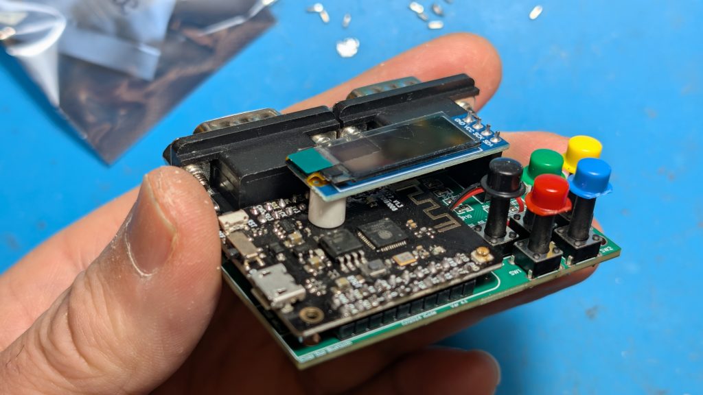
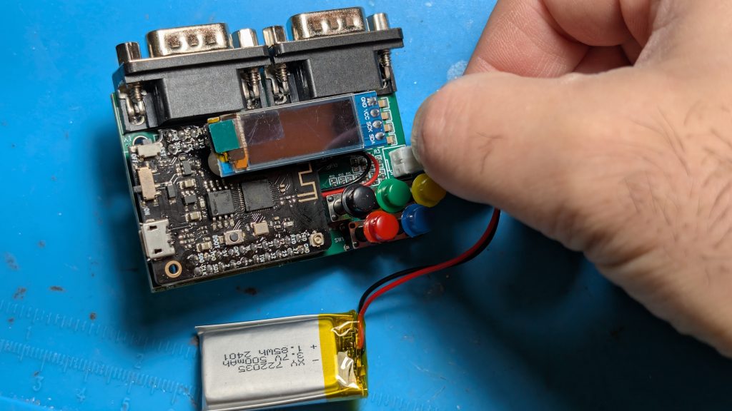
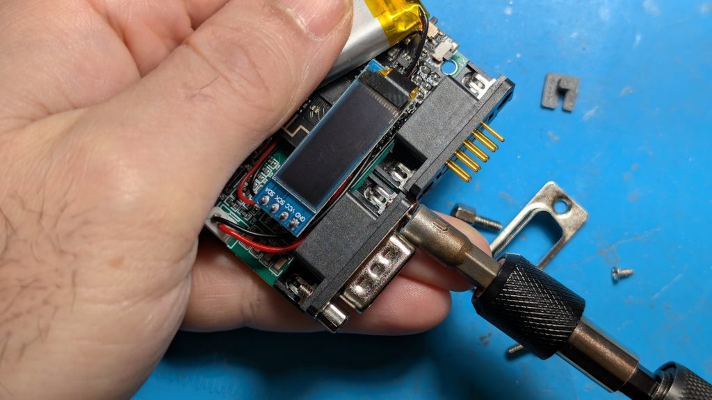
Assembling Duo Bluetooth DIY Kit

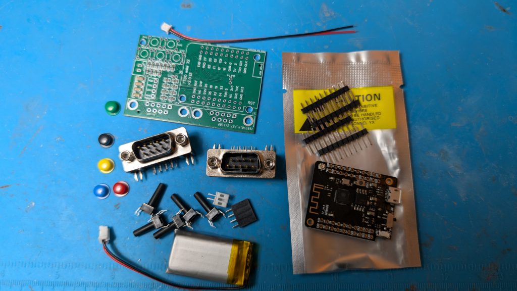
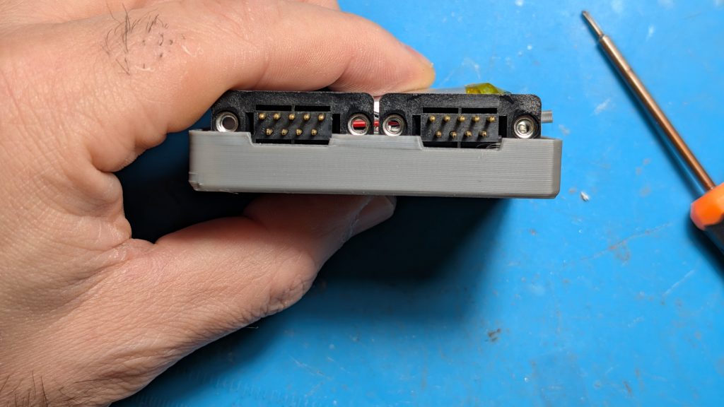
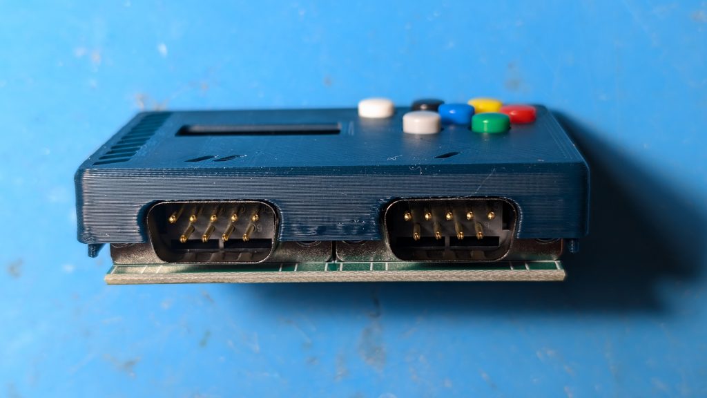
The unit comes with all the parts you need except the case and solder. you will need to 3D print the STL file, assemble the parts, and solder the components.  The Firmware is already loaded so you do not need to load any firmware.  

Step 1

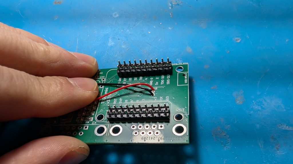
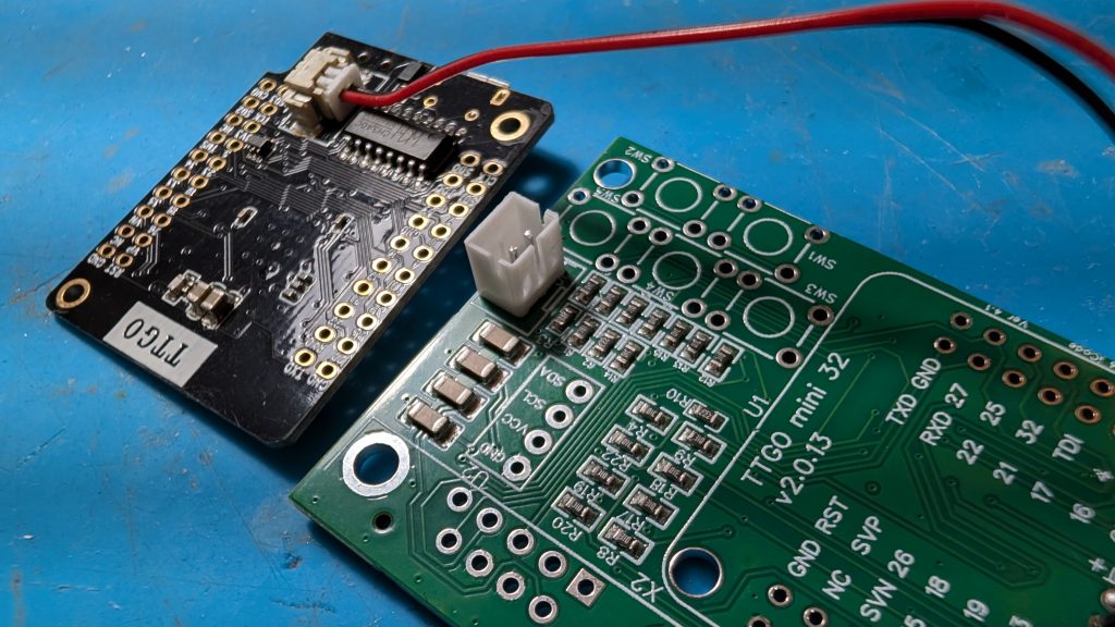
Insert the power connector cable to the PC board (Red to the BAT+ hole) and solder it from the bottom side. Also solder on the white male battery socket on the PC board as shown. 

Step 2

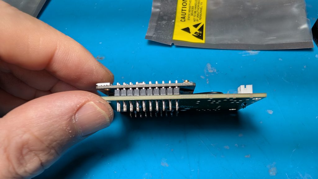
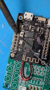
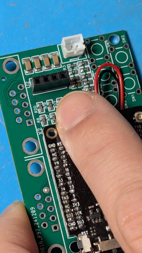
Place the daughter micro controller board on the PC board and make sure its level.  there will be a small gap as shown on the left picture.  The solder it as shown starting with the inner pins on both sides with soldering iron coming from the outside.  Be careful as you don’t want to touch any of the components on the micro controller board with your iron.

Step 3 & 4

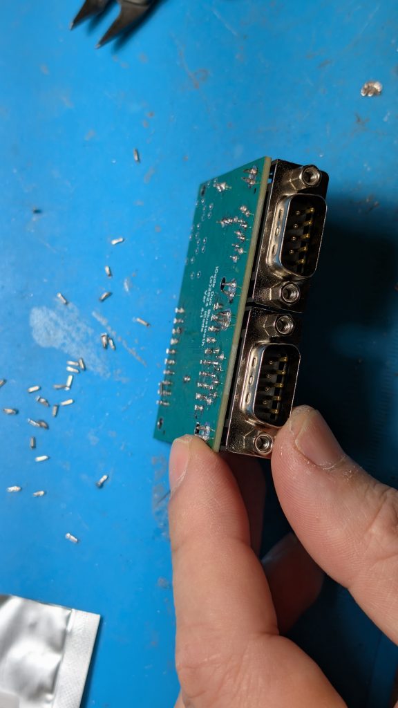
 Solder on the black 4 pin female connector. This is for the screen you will place on later.  

Solder on the two 9-pin right angle connectors as shown.

Step 5

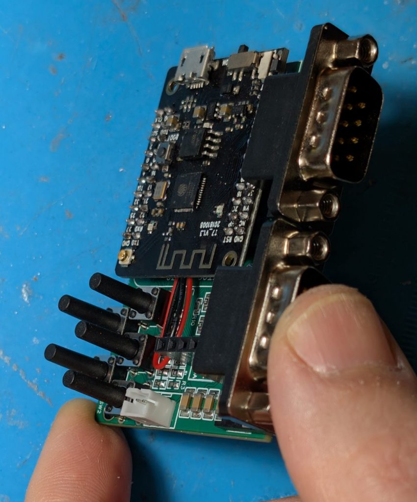
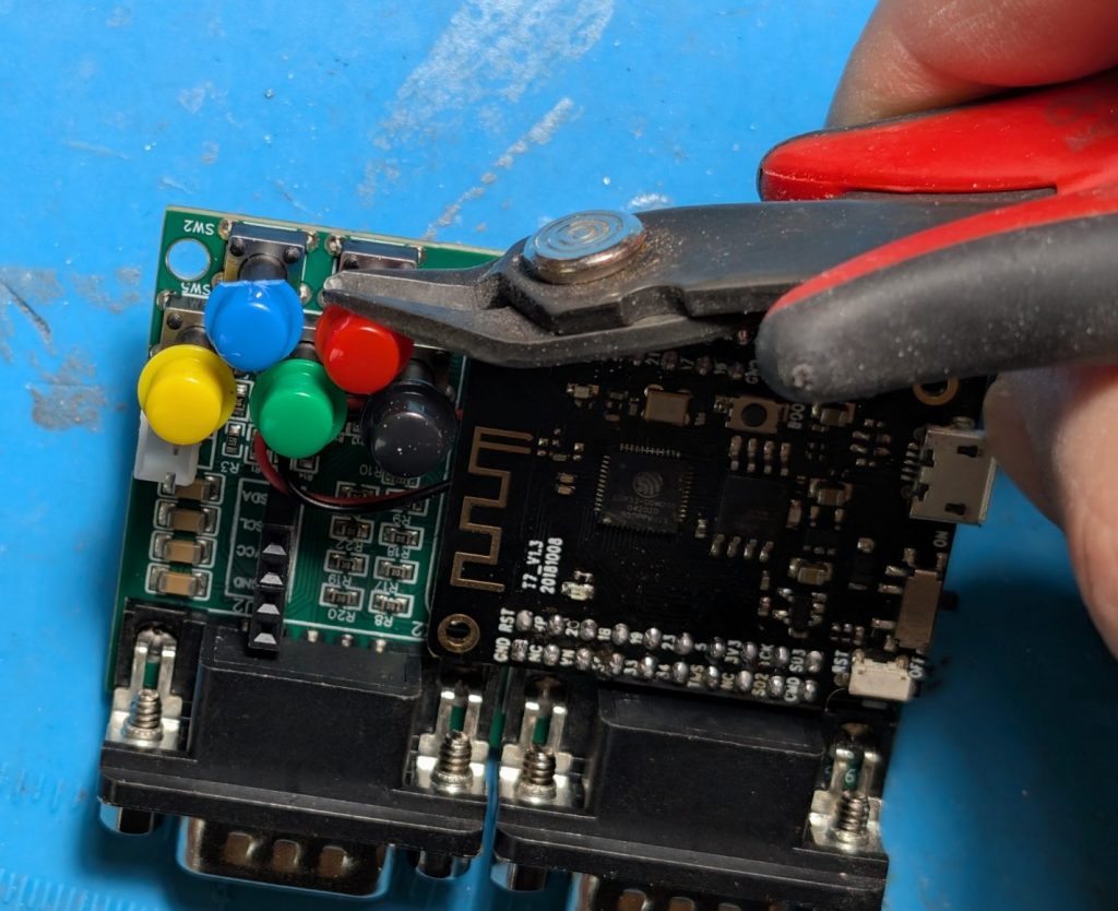
Place the the 5 switches and make sure hey are straight and then solder them on.  Place on the colored caps and if you place to use the case, trim the edges of the blue and red caps as shows so they don’t get in the way when we close the case later on. 

Step 6

Place the screen on and connect the battery.

Turn it on with the small on/off toggle switch on the side. 

You are done, unless you want to put the unit in a 3D printed case…

Steps 7 and 8 below are optional.

Step 7 

Download the STL file and 3d print the top and bottom.   You can get the STL file from here

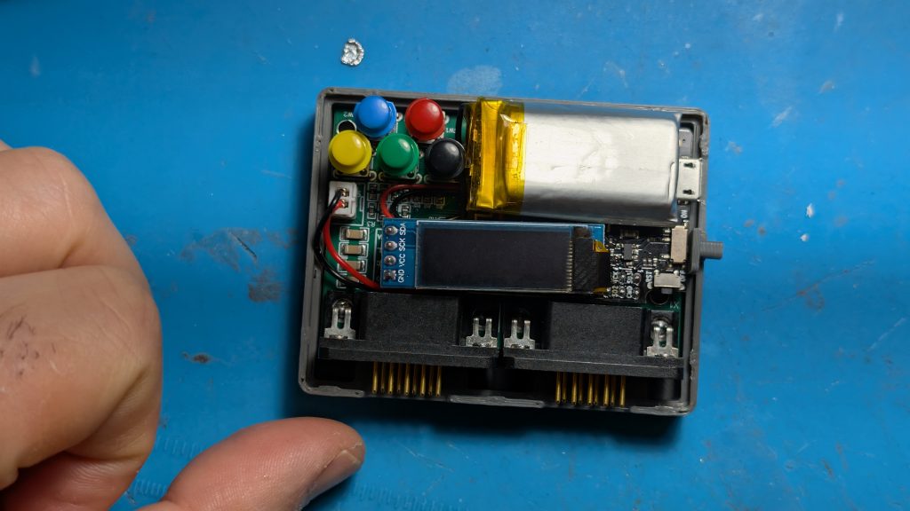
Take the metal protectors off the 9 pin connectors and the board and battery are positioned like show below in the bottom half of the case.

Step 8

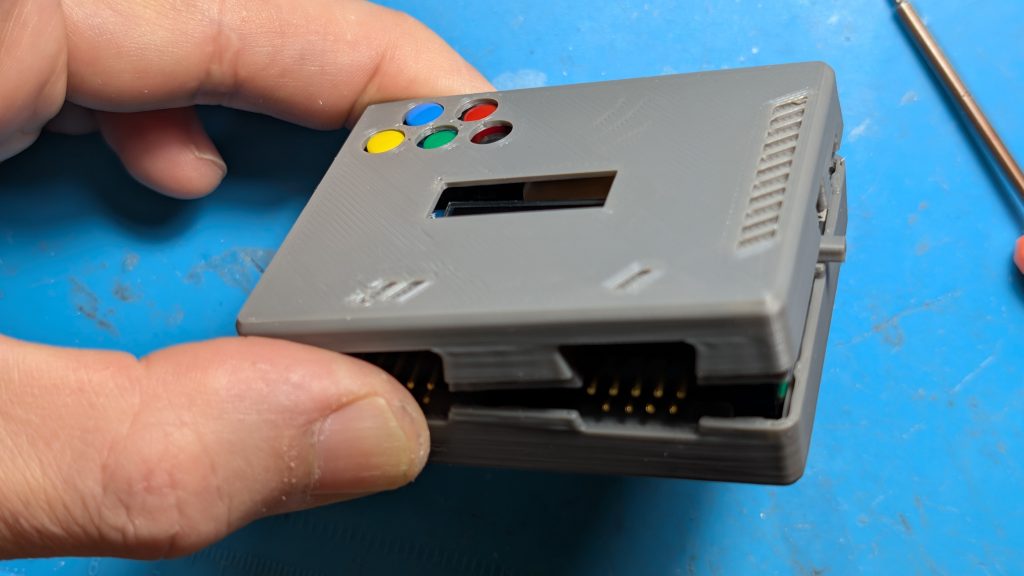
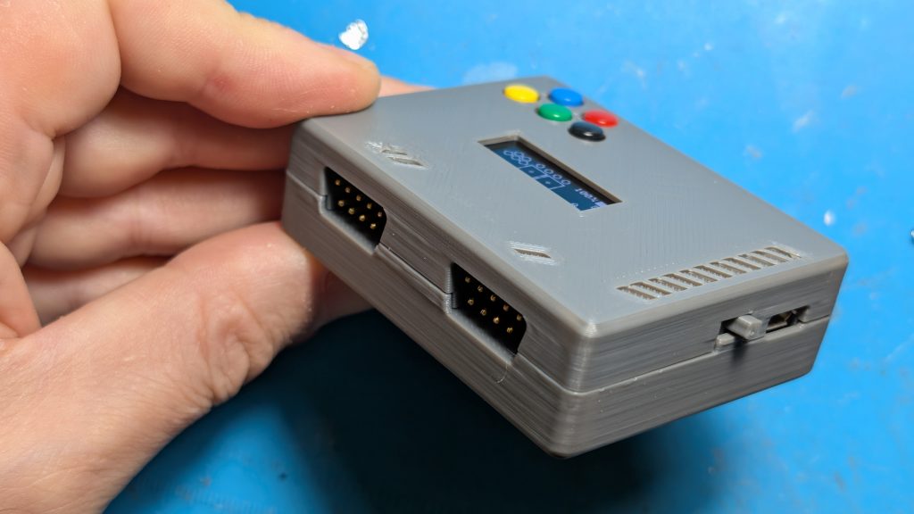
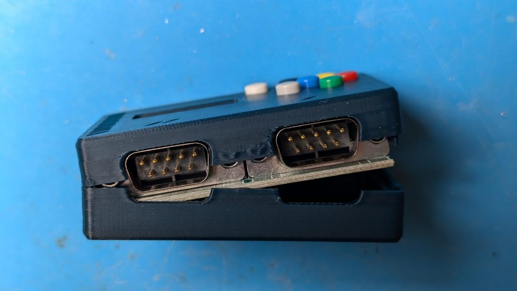
Add the top of the case from one side as shown and then the other end and snap together. 

Thats it!  

Assembling Duo Plus DIY Kit

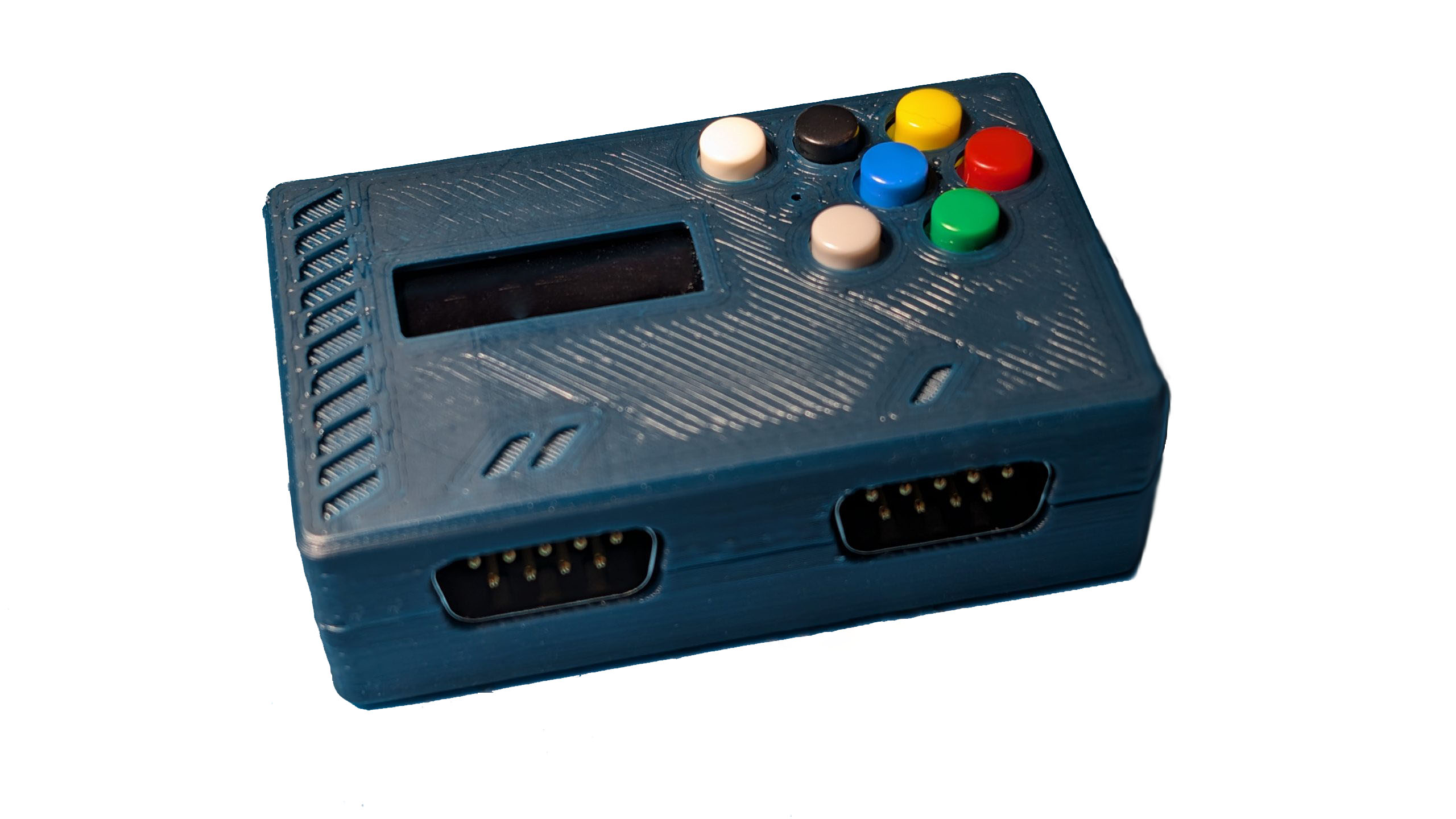
The unit comes with all the parts you need except the case and solder. you will need to 3D print the SDL file, assemble the parts, and solder the components.  The Firmware is already loaded so you do not need to load any firmware.  

Step 1

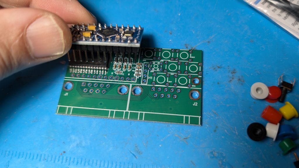
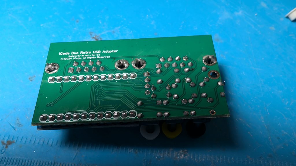
Insert the Pro Micro controller daughter board into the main board and solder all the pins.

Step 2

After you solder the pins, cut the pins so they don’t stick out.  Add the rest of components and solder them all.

Step 3

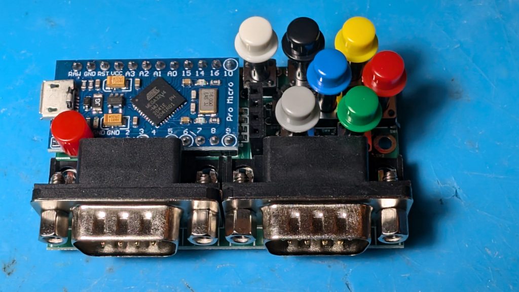
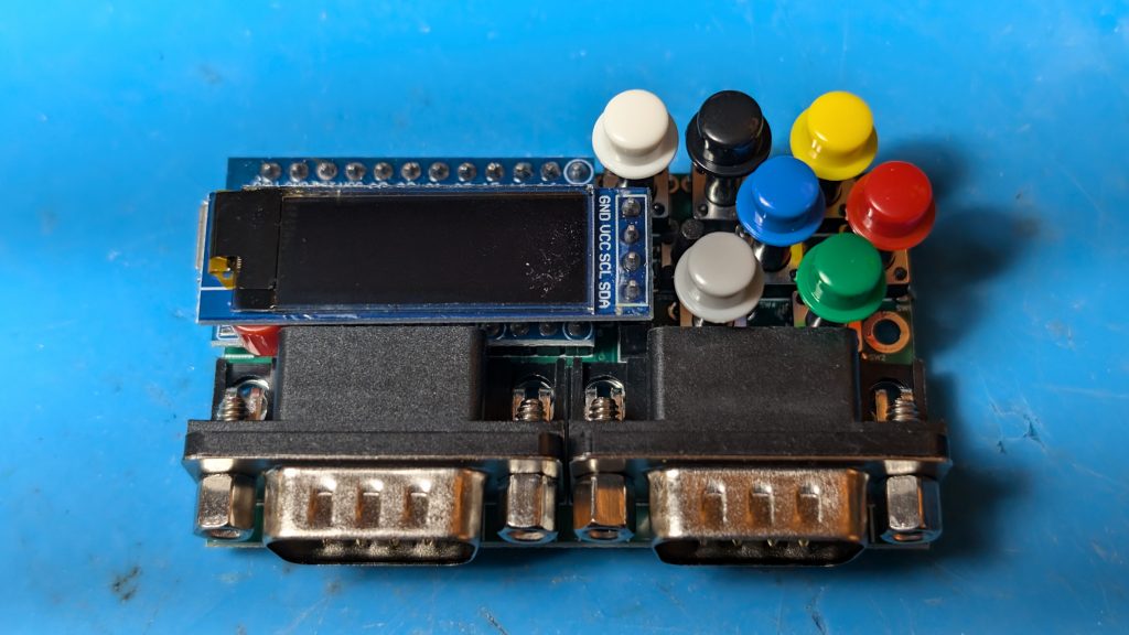
Place the colors caps on the switches as shown.  Note the Red cap on the daughter pro micro is a stand for the screen.

Step 4

Download the STL file and 3d print the top and bottom.   You can get the STL file from here

Add the top of the case first as shown on the picture below.

Step 5

Add the bottom of the case from one side as shown and then the other end and stap together. 

Thats it!  Connect the cord and plug into you USB port and enjoy.

Create RGB Rainbow Gradient with Programming Code

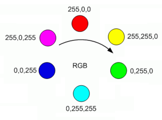
Here is some code that will help you create all the RGB values needed for generating a RGB Rainbow gradient. The code steps through 6 sets of transitions from one color to another in 256 steps each .

  • Red to Yellow
  • Yellow to Green
  • Green to Cyan
  • Cyan to Blue
  • Blue to Magenta
  • Magenta back to Red

With 6 transitions, each in 256 steps provides 1536 total colors and here is the result from the code below:

See it in action here:  https://codepen.io/alijani/pen/zYVmzqR


html file:

<canvas id="myCanvas" width="1536" height="200"></canvas>

Js File:

const canvas = document.getElementById("myCanvas");
const ctx = canvas.getContext("2d");

var x;
for (x=0; x<1536; x++) {          // 6*256
  ctx.fillStyle =  rainbow(x);
  ctx.fillRect(x, 0, x, 200);  
}


// Accepts values 0 through 1535 and returns the one of 1536 colors in rainbow.
function rainbow(x) {   
    let r = Math.trunc(x / 256);    // 0-5     
    let c = x % 256; 
   
    if (r==0) {
      value = rgb(255,c,0);        // red to yellow transition
    } else if (r==1) {
      value = rgb(255-c,255,0);    // yellow to green transition
    } else if (r==2) {
      value = rgb(0,255,c);        // green to cyan transition
    } else if (r==3) {
      value = rgb(0,255-c,255);    // cyan to blue transition
    } else if (r==4) {
      value = rgb(c,0,255);        // blue to magenta transition
    } else if (r==5) {
      value = rgb(255,0,255-c);    // Magenta to ren transision
    }
    return value;     
}

// simple function to convert rgb decimal values to #RRGGBB hex color string used in html
function rgb(r,g,b) {
  return "#"+(r).toString(16).padStart(2,'0')+(g).toString(16).padStart(2,'0')+(b).toString(16).padStart(2,'0');
}

How to Interface with Atari Driving Controller – Arduino Programming

The Atari driving controller uses a 16 position encoder that sends pulses to to pin 1 and pin 2 of the game port. These pulses can be deciphered or decoded to understand if the player is spinning the controller in the left or right direction.

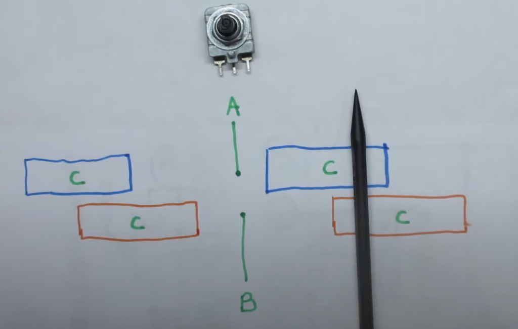
Here is how the spinners encoder works. If you look at the photo below, imagine point A is connected to Pin 1 and Point B is connector to Pin 2. As you spin the encoder the will make contact with the C blocks which are connected to common ground. So at the position shown, pin 1 (A) and Pin 2 (B) are not touching ground (C). but is you spin right, Pin 1 (A) will touch ground first but if you spin left, Pin 2 (B) will Touch ground first.

So if you are in the middle where A and B are not touching ground. you go from BA being 00 to 01, and if you spin a bit more you get to where the black pen is where the value becomes 11. Then if you keep going, you go to 10 and then back to 00.

Now if you spin left, you go from being 00 to 10, then 11, then 01.

All the programmer has to do is read the state of pin 1 and pin 2 continuously and compare it to its previous values to determine the direction the play turned. Here is a table that tells you if the player turned right or left based on the current and prior readings of pins 1 and 2.

With only 2 pins there are 4 possible combinations of values that Pin 1 and 2 can produce, like a 2 bit binary number.

Pin 2Pin 12 bit
Value
000
011
102
113
Previous
Value
Current
Value
Direction
01Right
13Right
20Right
32Right
02Left
10Left
23Left
31Left

Now we have all the logic we need to develop the pseudocode
  1. Get state of pins 1 and 2
  2. For current value, combine the pin values like binary bits and convert to decimal
  3. compare the current value to old value
  4. if the value has changed from perivious value,
    • Use table above to determine if you will move left or right
    • update the previous value to current value
  5. go back to step 1.

So all we need to do is connect pin 1 and 2 to pulled up IO ports of a micro controller. For the fire button, use pin 6 and connect it to a pulled up IO port. When the player presses fire button, pin 6 will go low. When the player spins, you can figure out easily if they spined right or left now!

Here is some sample code assuming you have used GPIO ports 1 for Pin 1, 2 for pin 2 and 3 for pin 6 (fire):

bool A;
bool B;
bool F;
int P=0;

void setup() {
    pinMode(1, INPUT_PULLUP);  
    pinMode(2, INPUT_PULLUP);  
    pinMode(3, INPUT_PULLUP);  
}

void loop() {
    A = !digitalRead(1);
    B = !digitalRead(2);
    F = !digitalRead(3);

    int V = A+B*2; 
    if (V != P) {
       if ((P==0 && V==1) || (P==1 && V==3) || (P==2 && V==0) || (P==3 && V==2)) {
           // Moved right code goes here
       } else if ((P==0 && V==2) || (P==1 && V==0) || (P==2 && V==3) || (P==3 && V==1)) {
           // Moved left code goes here
       }
       P = V;
    }
}

iCode Firmware Release 9 now available

iCode retro gaming USB adapters get a major upgrade with the release of its latest update, iCode Firmware 9, on Sunday, March 5th. This version brings a lot of new features, which should delight fans of retro video games!

On the hardware side, Firmware 9 is now compatible with the iCode USB models including the UNO, DUO, and QUAD. There are different Firmware 9 downloads specific to each hardware model and revision.

Among the most important new features, version 9 of firmware introduces a new menu navigation system to control all aspects of the device. Once configured, the device remembers all the changes and the last mode of operation, and it will return to the exact state even after a power cycle. This allows the device to be imbedded into arcade cabinets without having to have regular access to the device’s controls.

There has also been a variety of optimizations done which now deliver ultra-low latency play including use of paddles and trackballs.

Below is the list of changes for the release since the prior major release 8.

  • Plus editions now support Sega Genesis 3 button and 6 button Controllers. Also supports Start and Mode buttons. Must set settings menu “Console” to Genesis to activate. For Quad, H12 required. For some Duo Plus & Plus Pro H10 and below, special hardware mod may be needed. See iCode Community forums for details.
  • Device now remembers the mode you were in, even after a power cycle.
  • You can now see mode you are in even if display activity is turned off.
  • Device now remembers if your display was off even after a power cycle.
  • Optimized trackball and paddle mouse operation to provide much smother control. Keep display off for best experience when using mouse mode.
  • Device turns display always off when in trackball mode for optimized smooth trackball operation, unless you specifically turn on after in trackball mode.
  • Device no longer switches back to mode 1 when you access the menu system
  • When you switch target of where joystick or paddles to be reported to, system now correctly clears all gamepad values from prior target
  • Fixed buttons on paddles 3 and 4 on port 2 as they were reversed
  • Optimized auto paddle detection
  • Optimized screen display
  • Optimized Paddle auto calibration
  • Support for iCode Quad adapters
  • Full and Half duplex Paddle Modes
  • Added ColecoVision mode for Plus editions
  • New settings for paddle detection mode. OFF setting is useful for ColecoVision controllers
  • Added Keyboard on/off mode for Plus editions
  • Added compatibility with most recent update of MiSTer Atari 7800 core which changed paddle buttons. In MiSTer mode, Paddle buttons now register as button 3 which works correctly as fire button on Mister. In regular mode, paddle buttons on dual paddles connected to a single port will continue to register as button 0 and 1.
  • Fixed bug with mapping and display of buttons 8 through 32
  • Swapped default button maps for buttons 0 and 1. Red is now button 0, and Green is button 1 by default.
  • Revamped entire settings menu. You now have menus for paddles settings, main menu, and other settings.
  • Moved mister mode toggle to other settings menu
  • Removed mode 2 and common from UNO Devices
  • Improved auto-paddle detection when in MiSTer mode. Pressing yellow button.
  • Added status T indicator on display when in Mister mode
  • Fixed display not showing all inputs correctly after auto paddle updates
  • Fixed port 2 to report correct paddles order for dual paddles on the port.
  • In mouse mode, paddle buttons now correctly report to as mouse buttons.
  • When in mouse mode, paddles and trackballs now correctly only report as mouse and not gamepads
  • Added ability to set destination target as left / right or hat switch for Joystick and paddles data
  • Moved default paddles data to be reported as right hand stick instead of left to avoid conflict with joystick stick data which defaults to left hand.
  • Added developer menu that allows paddle data views. paddle sensor control, and more.
  • Added factory reset to developer menu

Search for products

Back to Top