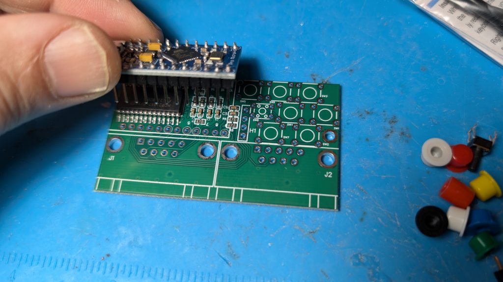
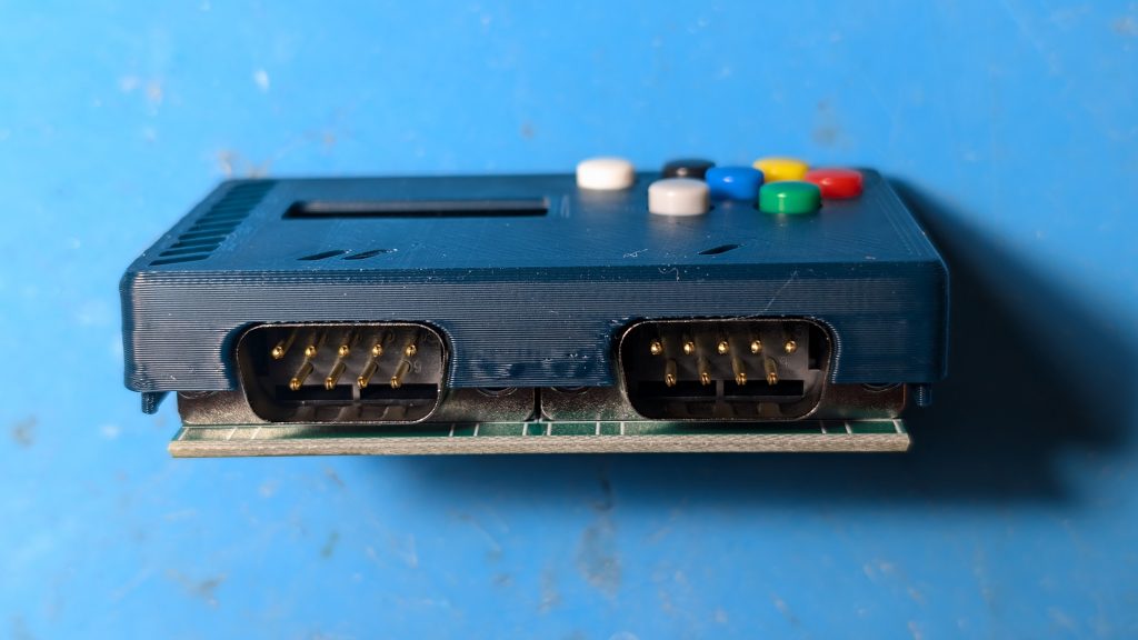
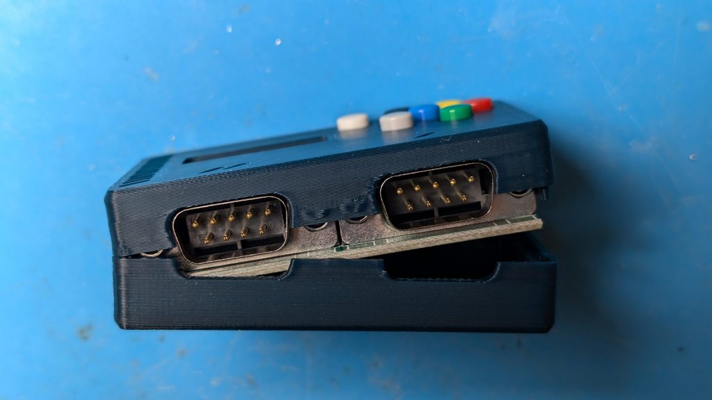
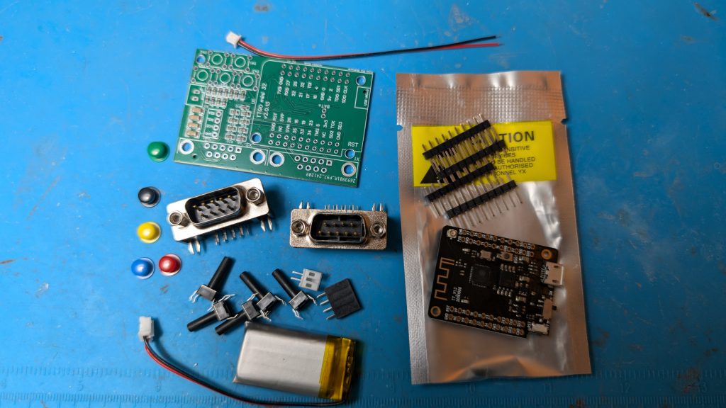
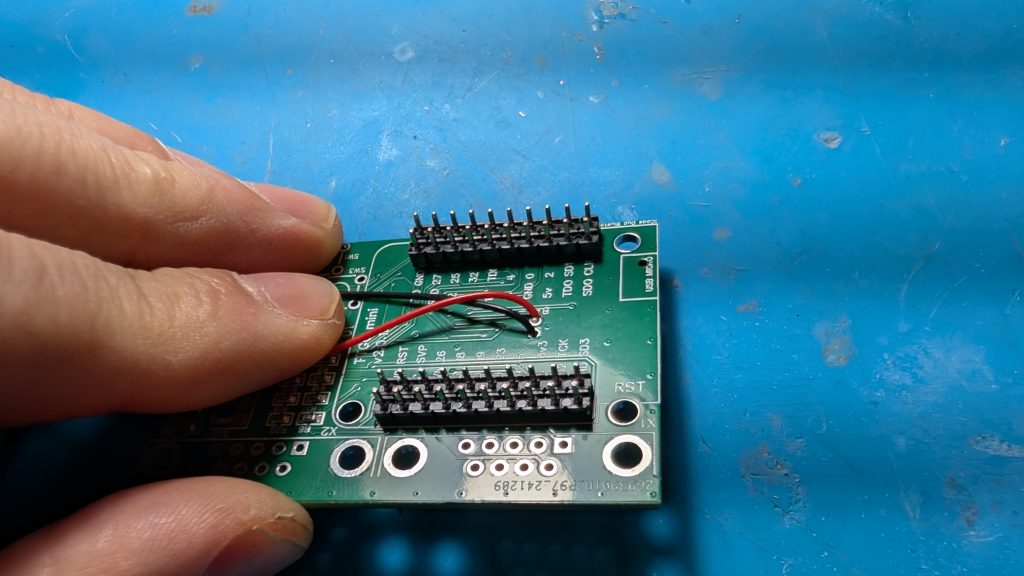
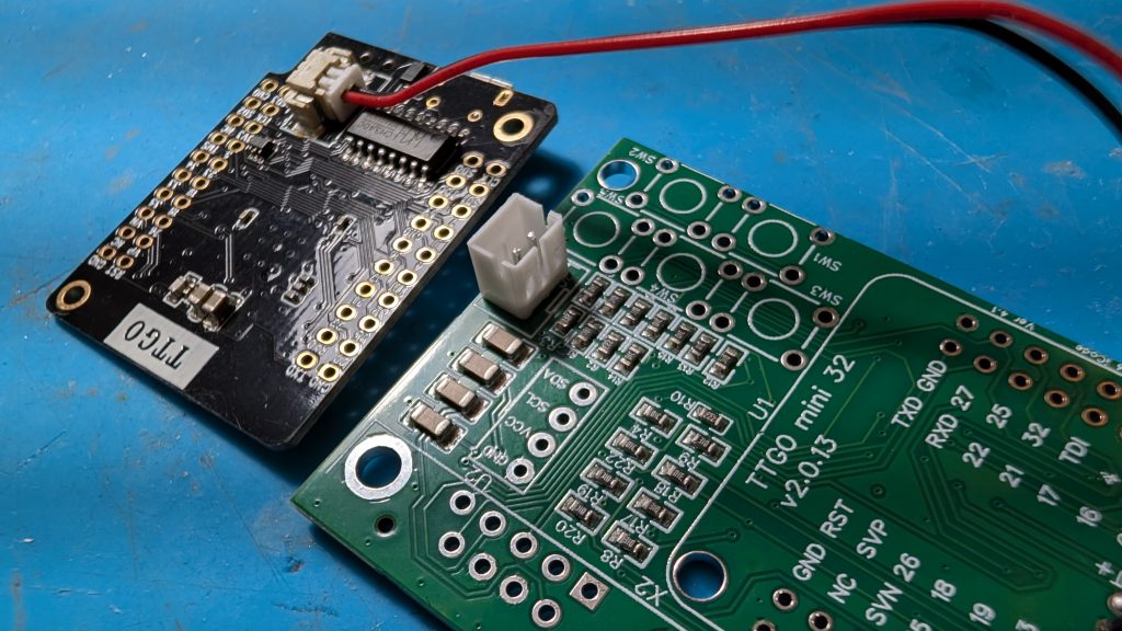
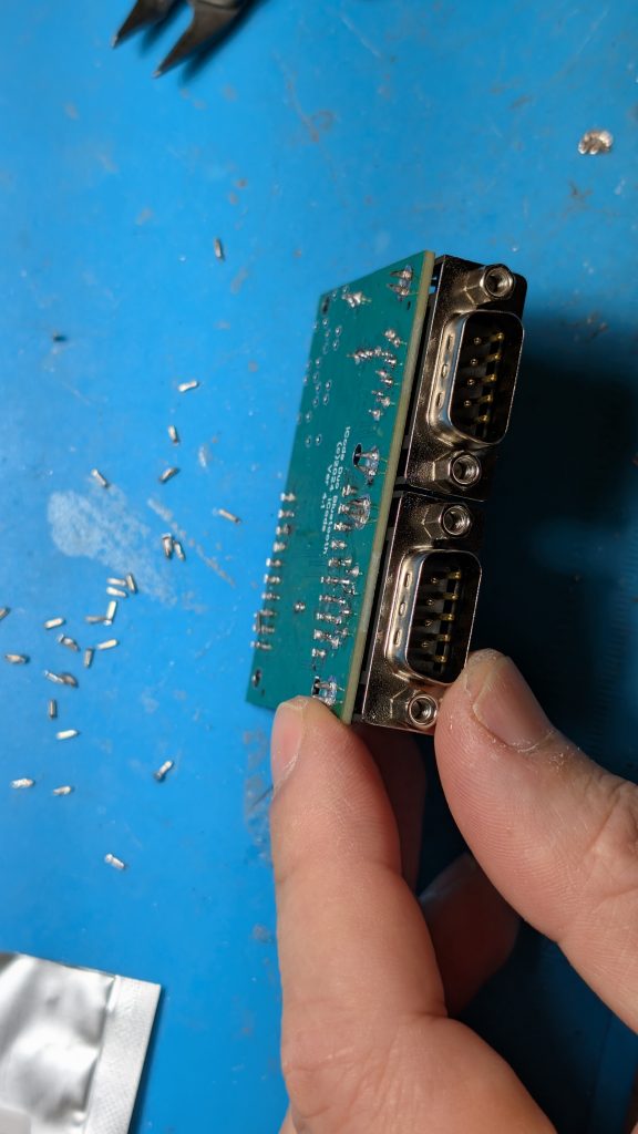
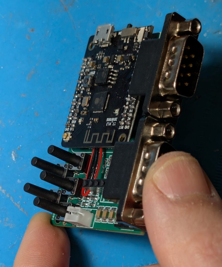
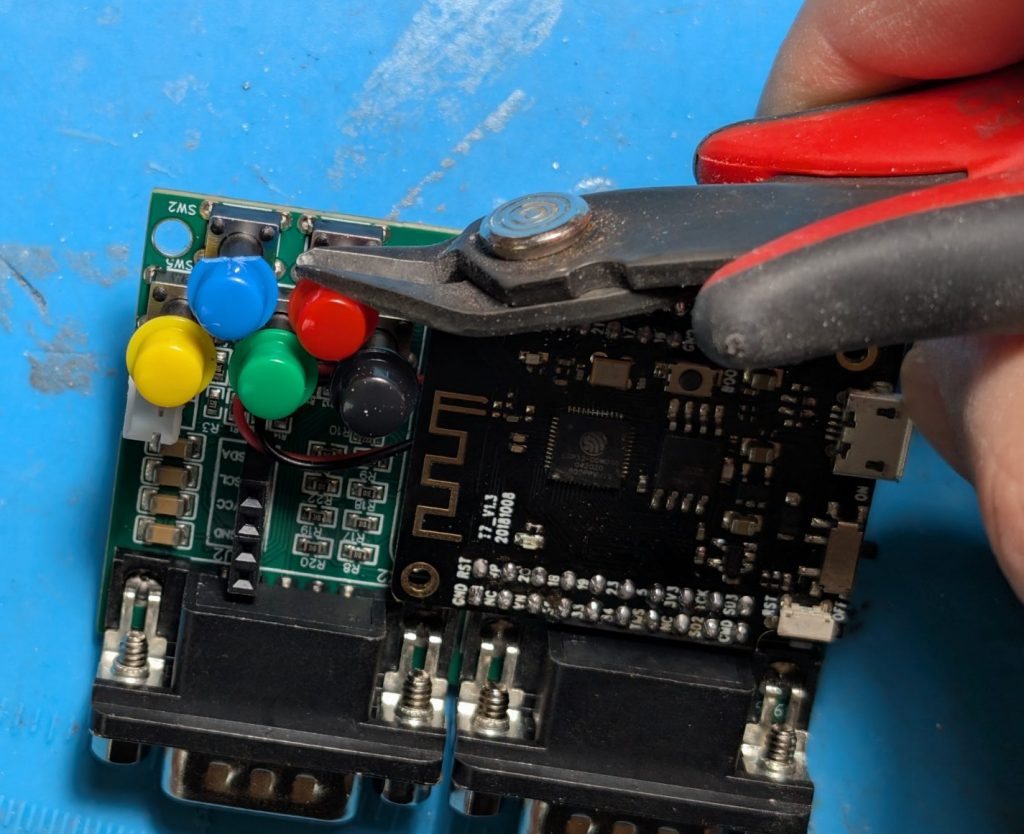
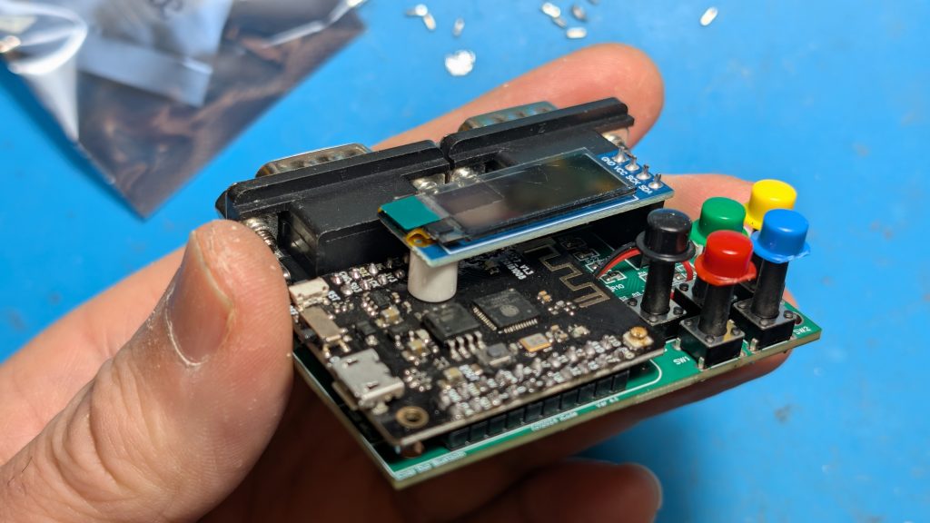
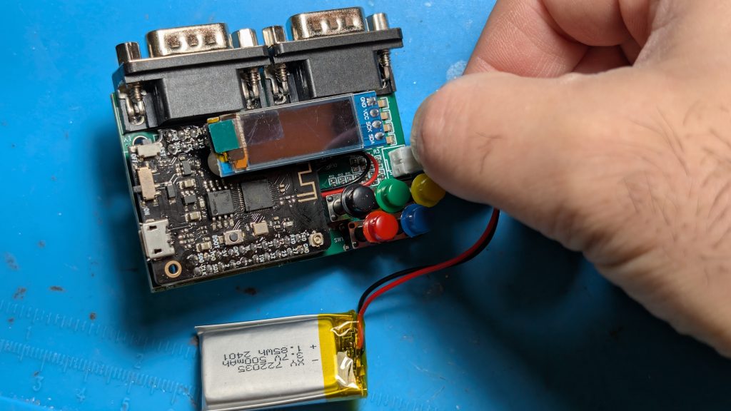
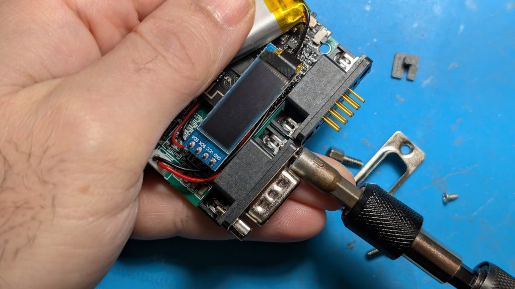
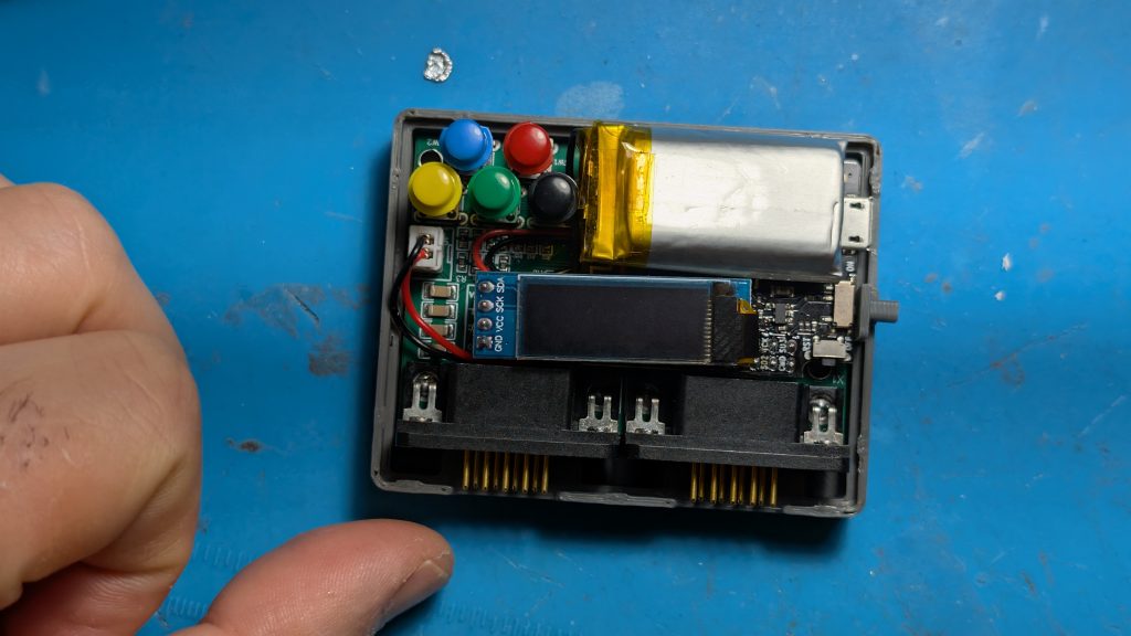
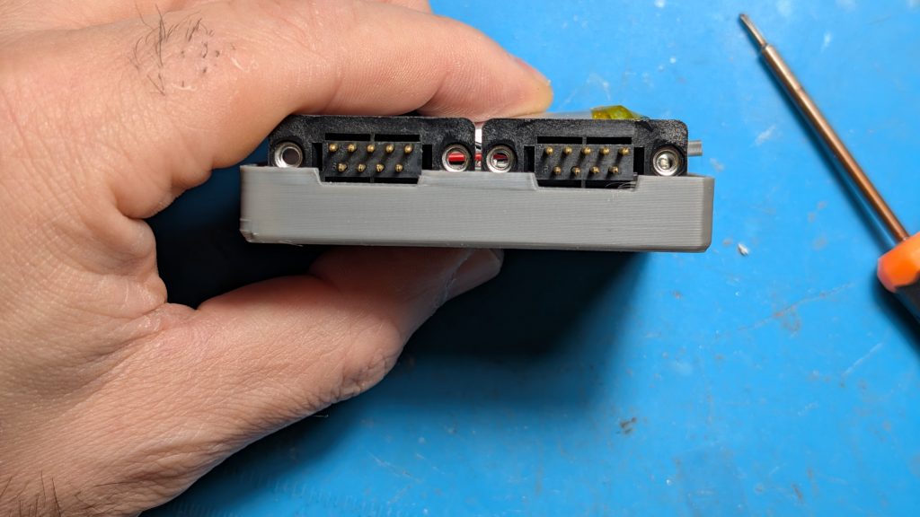
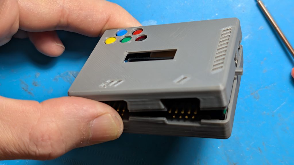
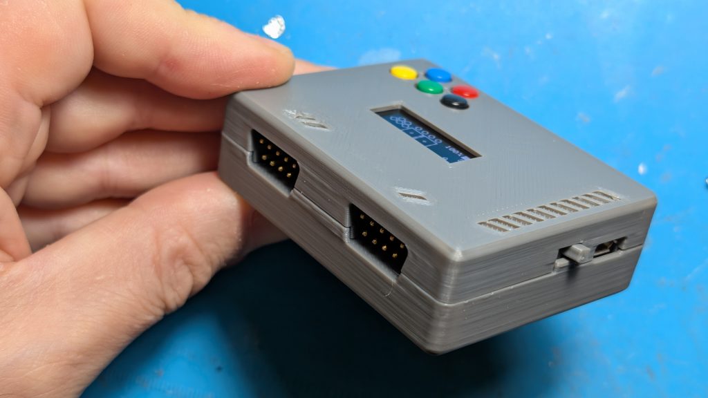
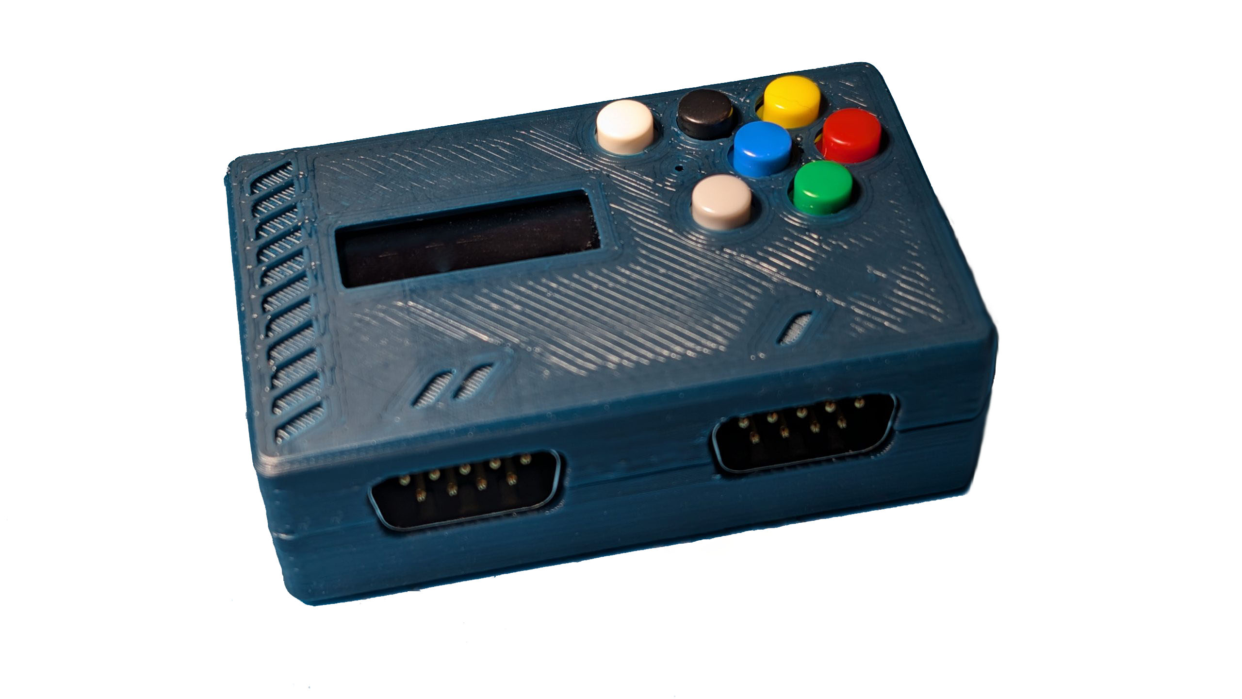
Assembling Duo Bluetooth DIY Kit

html file:
<canvas id="myCanvas" width="1536" height="200"></canvas>Js File:
const canvas = document.getElementById("myCanvas");
const ctx = canvas.getContext("2d");

var x;
for (x=0; x<1536; x++) {          // 6*256
  ctx.fillStyle =  rainbow(x);
  ctx.fillRect(x, 0, x, 200);
}


// Accepts values 0 through 1535 and returns the one of 1536 colors in rainbow.
function rainbow(x) {
    let r = Math.trunc(x / 256);    // 0-5
    let c = x % 256;

    if (r==0) {
      value = rgb(255,c,0);        // red to yellow transition
    } else if (r==1) {
      value = rgb(255-c,255,0);    // yellow to green transition
    } else if (r==2) {
      value = rgb(0,255,c);        // green to cyan transition
    } else if (r==3) {
      value = rgb(0,255-c,255);    // cyan to blue transition
    } else if (r==4) {
      value = rgb(c,0,255);        // blue to magenta transition
    } else if (r==5) {
      value = rgb(255,0,255-c);    // Magenta to ren transision
    }
    return value;
}

// simple function to convert rgb decimal values to #RRGGBB hex color string used in html
function rgb(r,g,b) {
  return "#"+(r).toString(16).padStart(2,'0')+(g).toString(16).padStart(2,'0')+(b).toString(16).padStart(2,'0');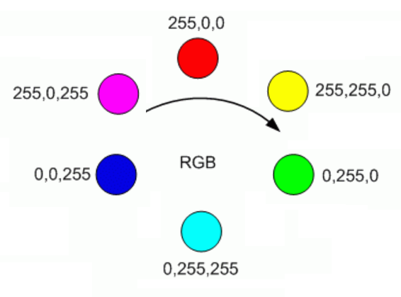
}The Atari driving controller uses a 16 position encoder that sends pulses to to pin 1 and pin 2 of the game port. These pulses can be deciphered or decoded to understand if the player is spinning the controller in the left or right direction.
Here is how the spinners encoder works. If you look at the photo below, imagine point A is connected to Pin 1 and Point B is connector to Pin 2. As you spin the encoder the will make contact with the C blocks which are connected to common ground. So at the position shown, pin 1 (A) and Pin 2 (B) are not touching ground (C). but is you spin right, Pin 1 (A) will touch ground first but if you spin left, Pin 2 (B) will Touch ground first.
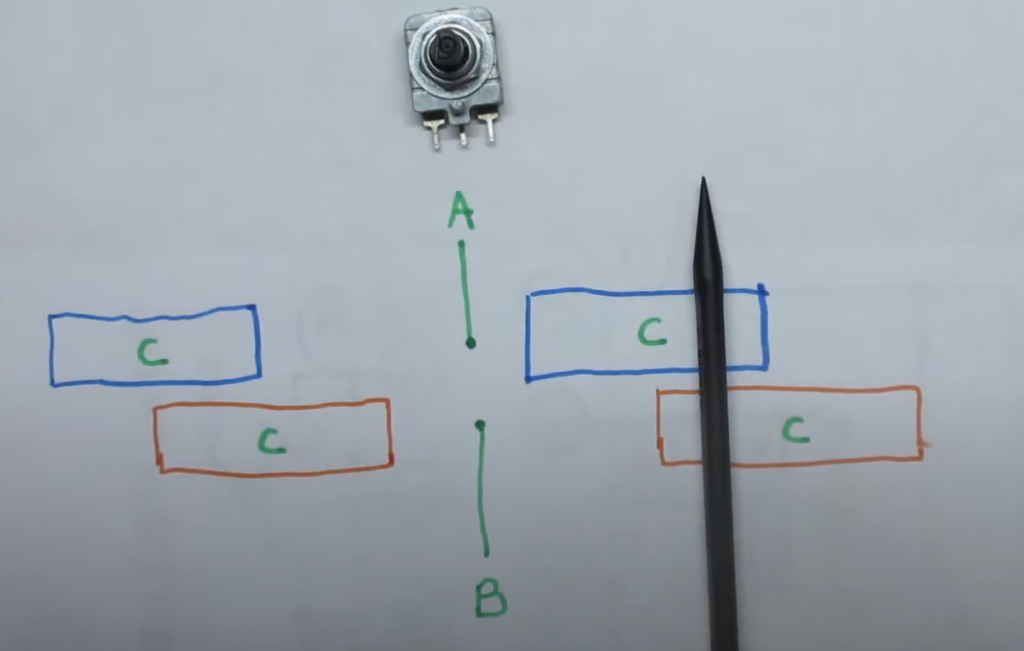
So if you are in the middle where A and B are not touching ground. you go from BA being 00 to 01, and if you spin a bit more you get to where the black pen is where the value becomes 11. Then if you keep going, you go to 10 and then back to 00.
Now if you spin left, you go from being 00 to 10, then 11, then 01.
All the programmer has to do is read the state of pin 1 and pin 2 continuously and compare it to its previous values to determine the direction the play turned. Here is a table that tells you if the player turned right or left based on the current and prior readings of pins 1 and 2.
With only 2 pins there are 4 possible combinations of values that Pin 1 and 2 can produce, like a 2 bit binary number.
| Pin 2 | Pin 1 | 2 bit Value |
| 0 | 0 | 0 |
| 0 | 1 | 1 |
| 1 | 0 | 2 |
| 1 | 1 | 3 |
| Previous Value | Current Value | Direction |
| 0 | 1 | Right |
| 1 | 3 | Right |
| 2 | 0 | Right |
| 3 | 2 | Right |
| 0 | 2 | Left |
| 1 | 0 | Left |
| 2 | 3 | Left |
| 3 | 1 | Left |
So all we need to do is connect pin 1 and 2 to pulled up IO ports of a micro controller. For the fire button, use pin 6 and connect it to a pulled up IO port. When the player presses fire button, pin 6 will go low. When the player spins, you can figure out easily if they spined right or left now!
Here is some sample code assuming you have used GPIO ports 1 for Pin 1, 2 for pin 2 and 3 for pin 6 (fire):
bool A;
bool B;
bool F;
int P=0;

void setup() {
    pinMode(1, INPUT_PULLUP);
    pinMode(2, INPUT_PULLUP);
    pinMode(3, INPUT_PULLUP);
}

void loop() {
    A = !digitalRead(1);
    B = !digitalRead(2);
    F = !digitalRead(3);

    int V = A+B*2;
    if (V != P) {
       if ((P==0 && V==1) || (P==1 && V==3) || (P==2 && V==0) || (P==3 && V==2)) {
           // Moved right code goes here
       } else if ((P==0 && V==2) || (P==1 && V==0) || (P==2 && V==3) || (P==3 && V==1)) {
           // Moved left code goes here
       }
       P = V;
    }
}
iCode retro gaming USB adapters get a major upgrade with the release of its latest update, iCode Firmware 9, on Sunday, March 5th. This version brings a lot of new features, which should delight fans of retro video games!
On the hardware side, Firmware 9 is now compatible with the iCode USB models including the UNO, DUO, and QUAD. There are different Firmware 9 downloads specific to each hardware model and revision.
Among the most important new features, version 9 of firmware introduces a new menu navigation system to control all aspects of the device. Once configured, the device remembers all the changes and the last mode of operation, and it will return to the exact state even after a power cycle. This allows the device to be imbedded into arcade cabinets without having to have regular access to the device’s controls.
There has also been a variety of optimizations done which now deliver ultra-low latency play including use of paddles and trackballs.
Below is the list of changes for the release since the prior major release 8.
Configuring RetroArch Stella 2014 core or Stella desktop emulators to work properly with Atari Paddles can be quite confusing. This guide will help you quickly configure both emulators iCode Duo retro adapters. I recommend Desktop Stella as it will be more responsive and easier to configure.
Coming Soon.
RetroArch has multiple cores that can emulate the Atari 2600. If you want to play paddle games, only the Stella 2014 core will work for you because its the only core that supports absolute positioning that is needed for paddle games. This feature was added to Stella 2014 core starting with version 3.9.3. Here is how you can load the right core and make sure you have the correct version:
Now that your core is loaded, lets make sure RetroArch sees your iCode Duo device and is setup properly.
Flashing and Booting from an EMMC module on an Odroid XU4 can be tricky. This is because you need a bootloader placed on a hidden Partition of the eMMC memory module. When you clean or flash an EMMC module with normal tools like Etcher or Rufus, you might delete the hidden partition that had the bootloader and the XU4 will simply not boot from your image even if the image you flashed is bootable.
While there are recovery images you can download that have the bootloader needed on it, most images you flash after that will still not contain the bootloader and you would be back to square 1.
The best was found to create a properly bootable EMMC is as follows:
What we are going to do now is use the linux dd command to copy the boot partition from your SD card to the appropriate area on the EMMC. Your EMMC device we want to write to is typically mmcblk0boot0 and it will be protected. So we first have to unlock it, then use the dd command as follows:
The last step might take a few seconds or minute. Once you see no more activity, you can now lock the partition again.
Now shutdown your XU4 and remove the SD card and flip the switch to boot from your EMMC!
This is what worked for me. Here is a screenshot of my session after step 4 of the first part.
If you were to take the knob or dial off of an electronic device, you might find a potentiometer underneath it. A potentiometer is a variable resistor, and the kind shown below changes resistance as the knob turns. This particular one has a resistance range from 0 ohms to 10,000 ohms.

RC circuit use combination of a resistor (R) and a capacitor (C) to control charge rate of a capacitor. One of the applications of RC circuits is to use a potentiometer as the resistor (R) and this allows you to control how it takes to charge the capacitor (C). The higher the resistance, the longer it takes for the capacitor to charge.

These two components together form an RC (resistor-capacitor) circuit. When the switch is turned on, the capacitor begins to charge. The charge rate always follows the following standard RC charging curve.

The amount of time it takes for charging the capacitor to 63.2% can be calculated using the formula T = R*C in seconds. So for above T = R*C = 100k x 22uF = 2.2 Seconds to get to the 1T line.
TTL circuits on micro controllers typically have a threshold voltage of 1.6V before they recognize an input as HIGH.
So what you can do is connect a digital port to the + side of the capacitor (Vc). Set the port to INPUT mode and force it to LOW. This will discharge the capacitor and immediately the capacitor will begin to charge. Now in a tight loop, just count up from zero and read the PIN till it goas high.
pinMode(pinVC, INPUT);
digitalWrite(A0, LOW); // this will discharge the capacitor
Int i=0; While (! digitalread(PinVC)) { i++; }
The value of i will vary based on how you turn the knob!
To calculate how long it takes for the capacitor to get to a certain voltage you can use the following: t = -ln((Vs-Vc)/Vs)R*C
ln mean natural log or log base e, Vs is the supply voltage, and Vc is the voltage across capacitor
For example, an Atari Paddle uses a 1 Meg ohm resistor. Say we wanted to read the paddles at least 30 times per second using a 5v microcontroller board. What value of capacitor should we use? If you use a 1 Meg Ohm Pot and a 5v board with 1.6 volts being the TTL threshold voltage, a capacitor of 0.068uF, it will take 26.23ms for the pin to go high at the max pot value. – ln((5-1.6)/5)*1000000*0.000000068 = 26.23ms This means you can read it ~38 times per second (1000 / 26.23). Since NTSC frame rate is about 30 frames per second, this will allow you to read it at least once per frame! This is probably why Atari hardware uses a 0.068uF capacitor in its RC circuit
Flashing micro controllers with Arduino IDE or Platform.io are fairly simple when you have the source code of your sketch but there are times where all you have is the HEX file and you need a simple way to program your Pro Micro or other micro controllers quickly.
Both Arduino and Platform.io use a program called AVRDude in the background for flash but figuring our all the parameters and what come ports to use with AVRDude can also get quite complex standalone.
So, I found a much easier way to to use a minimal version of AVRDude and I created a simple command you can run at the command prompt to flash your Pro Micro.
All you have to do is:
That’s it. You will see something like below and you are DONE!

If you are wondering how this works or if you have trouble, here is a step by step details of what the PROG command does. PROG is a batch file PROG.BAT in the same folder that runs a series of commands. In short:
PROG looks for the Pro Micro attached to your PC by searching for a device called “USB Serial Device” to see what COM port it is. If you open up your device manager, you will see something like this. As you can see mine is on COM8.

If it was a Blank one, it would instead say “Arduino Leonardo” and why you need to use PROGB instead as it searches for Arduino Leonardo instead of USB Serial Device.

Now that it knows which COM port the device is on, it resets that port with command: mode COM8: baud=12 > nul
This causes the Pro Micro to go into bootloader mode for about 8 seconds. If you have device manager open, you will see the device change to something like this:

As you can see, it now in boot loader mode and its on COM4.
If for some reason it does not go to bootloader mode, you can manually force the Pro micro into this mode by shorting RST and GND pins for a quick second while its plugged in.
In some cases, the bootloader may not be present and this means we cant reset the device with com ports.
To manually force the update:


When it all fails, you can just directly force the firmware update as follows.